
RFI-Free Ringer Generator Works Off Single 5-V Supply

The circuit design leverages the LM4871's capabilities to generate a robust ringing voltage suitable for POTS (Plain Old Telephone Service) applications. The configuration of the op-amp as an inverting gain stage allows for effective sine-wave generation through the phase-shift network, which is critical for producing the desired ringing tone. The choice of passive components, particularly the resistors and capacitors, plays a vital role in determining the oscillation frequency and waveform characteristics. The use of ceramic capacitors for stability and tantalum capacitors for bypassing ensures reliable operation and minimizes noise interference.
The transformer selection is also crucial, as it must provide adequate voltage and current without saturation, particularly under load conditions typical of telephone ringers. The design accommodates variations in frequency, allowing for flexibility in applications that may require different ringing frequencies. The ability to control the ringing bursts through a CMOS-level pulse enables integration with digital systems, enhancing the circuit's versatility.
Overall, this circuit exemplifies a practical approach to generating ringing voltage for telephone systems, balancing simplicity and effectiveness while ensuring compliance with industry standards. The detailed specifications of component values and configurations provide a clear framework for implementation, making it accessible for engineers and technicians in the field.A simple yet effective circuit to generate a POTS-compatible ringing voltage can be made from National Semiconductor`s LM4871 audio-amplifier IC and a dozen passive components ( see the figure ). This circuit delivers 1 W of sine-wave output at about 70 V rms. This is sufficient to power most ordinary telephone ringers. The op-amp section of the L M4871 (pins 3, 4, and 5) is connected as an inverting gain stage. The stage functions as a sine-wave oscillator thanks to the phase-shift network, which consists of resistors R1, R2, and R3; and capacitors C1, C2, and C3. The noninverting input is biased by the built-in rail splitter on pin 2, and R3 doubles as the input resistor.
Therefore, the ratio of feedback resistor R4 to R3 determines gain. The values shown represent a compromise between waveform purity and robust oscillation. Ceramic capacitor C4 counteracts the LM4871`s tendency to break into spurious high-frequency oscillation at certain output voltages. Bypass capacitors C5 and C6 are inexpensive, solid-tantalum types. T1 can be an ordinary, off-the-shelf, 60-Hz power transformer, such as the Triad FS12-500, designed to yield 6.
3 V rms at 600 mA or more from a 220- to 240-V source. The derating factors appropriate for sub-design-frequency operation have been applied. As shown, the circuit oscillates at approximately 20 Hz. It can be retuned to about 25 Hz by scaling resistors R1, R2, and R3 down to 24. 3 k ©; and R4 to 845 k ©. Although a conventional mechanical ringer forms a resonant circuit with its blocking capacitor, frequency isn`t extremely critical in most ringer applications. To signal devices that accept both the 20- and 25-Hz standards, the oscillator may be designed for 22.
5 Hz (R1, R2, and R3 at 27. 4 k © and R4 at 953 k ©), permitting adequate frequency stability using inexpensive, 10% tolerance, polyester capacitors for C1, C2, and C3. The ringing-voltage burst timing is conveniently controlled by applying a 5-V CMOS-level pulse to the Enable input.
If this input is driven high (or left open), the LM4871 shuts down so that the circuit`s total current drain is under 1 µA. When the input is pulled below 0. 5 V, the oscillator starts smoothly, reaching full amplitude in 300 ms. Usually the start time isn`t much of an issue because ringing bursts typically last at least one second.
🔗 External reference
Related Circuits
The supply receives -20 V from the rectifier/filter which is fed to the collector of the Darlington pnp pass transistor, a TIP105. The base drive to the TIP105 is supplied through resistor R5. The base of the TIP is...
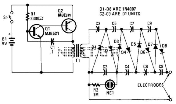
This circuit consists of components Q1, Q2, R1, and C1, which together create a multivibrator. The oscillation produced results in a square wave with a voltage peak-to-peak (Vpp) ranging from 20 to 30 volts. This output is then amplified...
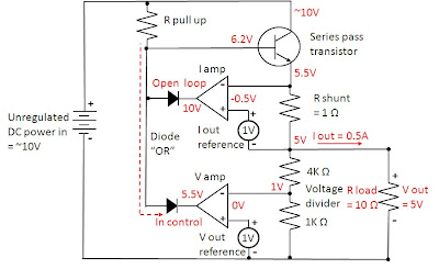
Most power supplies regulate either their output voltage or current at a constant level, depending on the load resistance relative to the power supply's output voltage and current settings. This can be summarized as follows: To accomplish this, most...
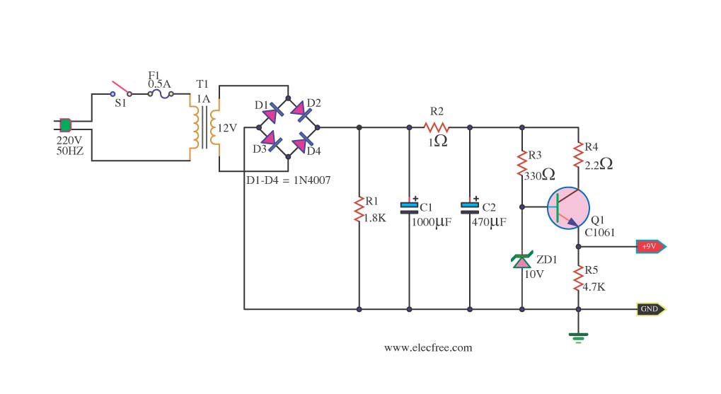
This is a DC power supply circuit designed to regulate 9 volts and provide a current output ranging from 1 amp to 2 amps. The circuit utilizes a modified TIP31 transistor, although alternative transistors such as TIP41, MJE3055, or...

A simple lab power supply electronic project can be designed using this circuit diagram, which is based on the LM2576 monolithic integrated regulator that provides all the active functions for a step-down (buck) switching regulator. As seen in the...
This circuit primarily relies on the regulator for its functionality. The 78S09 regulator can provide a continuous output of up to 2 amps while ensuring a low noise and well-regulated supply. Although the circuit can operate without additional components,...