
bh1417f fm stereo transmitter electronic project

The BH1417F FM stereo transmitter IC is a versatile component that integrates both the stereo modulation and transmission functions within a single chip. The stereo modulator's ability to generate composite signals is essential for maintaining audio quality during transmission. The MAIN signal carries the primary audio content, while the SUB signal provides additional stereo information, and the pilot signal, generated from the 38kHz oscillator, is crucial for demodulation at the receiver end.
The circuit's design allows for a range of applications, particularly in personal broadcasting scenarios where users wish to transmit audio wirelessly within a limited distance. The effective range of approximately 20 meters makes it suitable for home use, allowing music to be streamed to various locations within a residence or small venue without the need for extensive wiring.
The construction of the L1 coil is a critical aspect of the transmitter's performance. The specified 2.5 turns of enamelled copper wire ensure that the coil is capable of generating the necessary inductance for efficient operation. The use of an F29 ferrite slug enhances the coil's magnetic properties, improving the overall efficiency of the transmitter. The option to use a commercially available variable coil provides flexibility in tuning the transmitter for optimal performance, allowing users to adjust the frequency as needed to avoid interference with other signals.
Overall, this circuit design exemplifies an effective approach to FM transmission, combining ease of use with quality audio performance, making it a valuable tool for hobbyists and professionals alike in the field of wireless audio broadcasting.This stereo FM stereo modulator circuit use the BH1417F FM stereo transmitter IC which consists of a stereo modulator for generating stereo composite signals and a FM transmitter for broadcasting a FM signal on the air. The stereo modulator generates a composite signal which consists of the MAIN, SUB, and pilot signal from a 38kHz oscillator.
This BH1417F stereo FM transmitter is capable of broadcasting good quality signals over a range of about 20 meters and is ideal for broadcasting music from a CD player or from any other signal source so that it can be picked up in another location. L1 coil comprises 2. 5 turns of 0. 5 - 1mm enamelled copper wire (ECW) wound onto a tapped coil former fitted with an F29 ferrite slug. Alternatively, you may also use any commercially made 2. 5 turns variable coil. 🔗 External reference
Related Circuits
The SW transmitter circuit is based on the IC BEL1895 and operates in the shortwave HF band (6 MHz to 15 MHz). It is suitable for short-range communication and educational purposes. The circuit comprises a microphone amplifier, a variable...
Modern ICON electronic engine controls from BRP The ICON electronic engine control system developed by Bombardier Recreational Products (BRP) represents a significant advancement in marine technology. This system integrates sophisticated electronic controls to enhance the performance and reliability of marine...
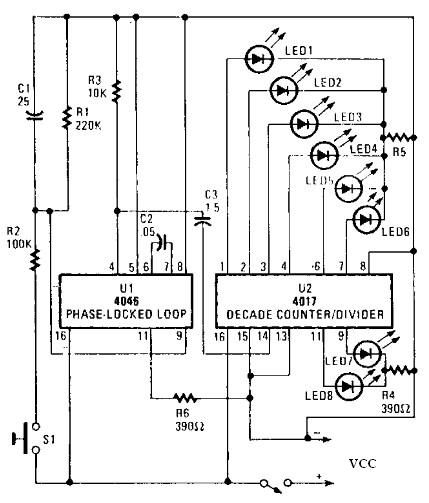
An electronic circuit for a roulette wheel can be constructed using a 4046 Phase-Locked Loop (PLL) that includes a Voltage Controlled Oscillator (VCO), two phase comparators, a source follower, and a Zener diode to generate a low-frequency pulsed output...
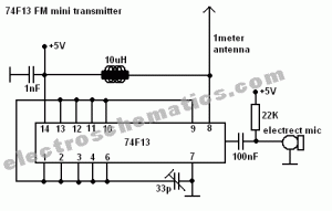
This FM spy transmitter can function as a bug transmitter or a DIY FM bug. It utilizes a single IC 74F13, one coil, a capacitor, and one additional component. The FM spy transmitter is a compact device designed for covert...
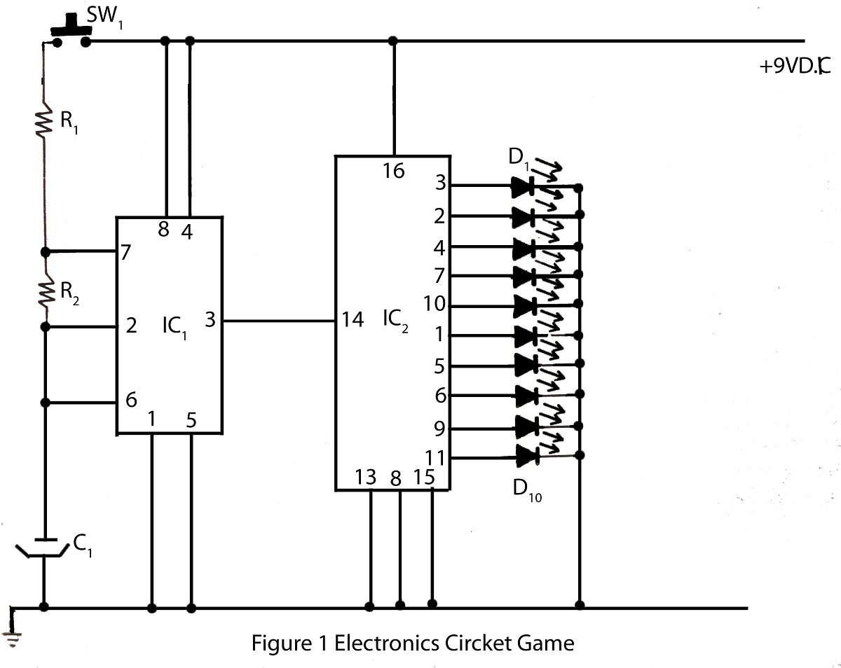
The electronics cricket game circuit presented on this website is a straightforward and easy-to-build circuit diagram for an electronics cricket project, as well as various other game projects. The electronics cricket game circuit typically consists of several key components that...
This project indicates the audio volume level going to speakers by illuminating LEDs. The LEDs can be of any color, allowing for creative combinations. The circuit input is connected to the speaker output of an audio amplifier. Two identical...