
Simple Stereo VU Meter

This audio level indicator circuit utilizes LEDs to visually represent the volume levels of audio signals from an amplifier. The design requires two identical circuits to monitor both the left and right audio channels, ensuring a comprehensive audio visualization. The input connection is made to the speaker output of the amplifier, which allows the circuit to respond to the audio signal levels directly.
The core component of the circuit is a 10k ohm variable resistor (VR), which enables the user to adjust the sensitivity of the input signal. This feature is essential for tailoring the circuit's response to different audio sources and desired brightness levels of the LEDs. The flexibility of using various colored LEDs enhances the aesthetic appeal of the project, allowing for a customized display.
For larger installations, an optional output transistor can be integrated into the design. This transistor serves to amplify the current, allowing the circuit to drive multiple LEDs concurrently, which is particularly useful for larger displays or installations. The capability to light up three LEDs per channel provides a dynamic visual representation of audio levels, with the sequence of illumination carefully designed to create an engaging effect.
The lighting sequence for the LEDs is predetermined, following a specific order: Pin 1, 18, 17, 16, 15, 14, 13, 12, 11, and 10. This sequence ensures a smooth transition of lights, reflecting the audio signal's amplitude in a visually appealing manner. Overall, this project combines functionality with creativity, resulting in an attractive and informative audio level indicator.This project will indicate the volume level of the audio going to your speakers by lighting up LEDS. The LEDS can be any color so mix them up and really make it look good. The input of the circuit is connected to the speaker output of your audio amplifier. You want to build two identical units to indicate both right and left channels. The input signal level is adjusted by the 10k ohm VR. If you wish to make a very large scale model of this unit and hang it on your wall there is an optional output transistor that can drive many LEDS at once. The unit I built drove three LEDS for each output. The sequence of the LEDS lighting are as follows Pin 1, 18, 17, 16, 15, 14, 13, 12, 11, 10. 🔗 External reference
Related Circuits
Due to their speed, accuracy, effectiveness, and cost-efficiency, infrared (IR) digital thermometers have supplanted traditional mercury thermometers. An ear digital thermometer utilizes a thermopile sensor to measure the infrared heat emitted by the eardrum, which correlates with the temperature...
This circuit was requested by a school teacher. It is a simple intercom that anyone can assemble and operate. It is based on the LM380 integrated circuit (IC). The intercom circuit utilizing the LM380 IC is designed for straightforward assembly...
This surround-sound decoder is based on the "Hafler" principle, first discovered by David Hafler in the early 1970s. The original idea was to connect a pair of speakers for use as rear speakers in a surround setup. While this...
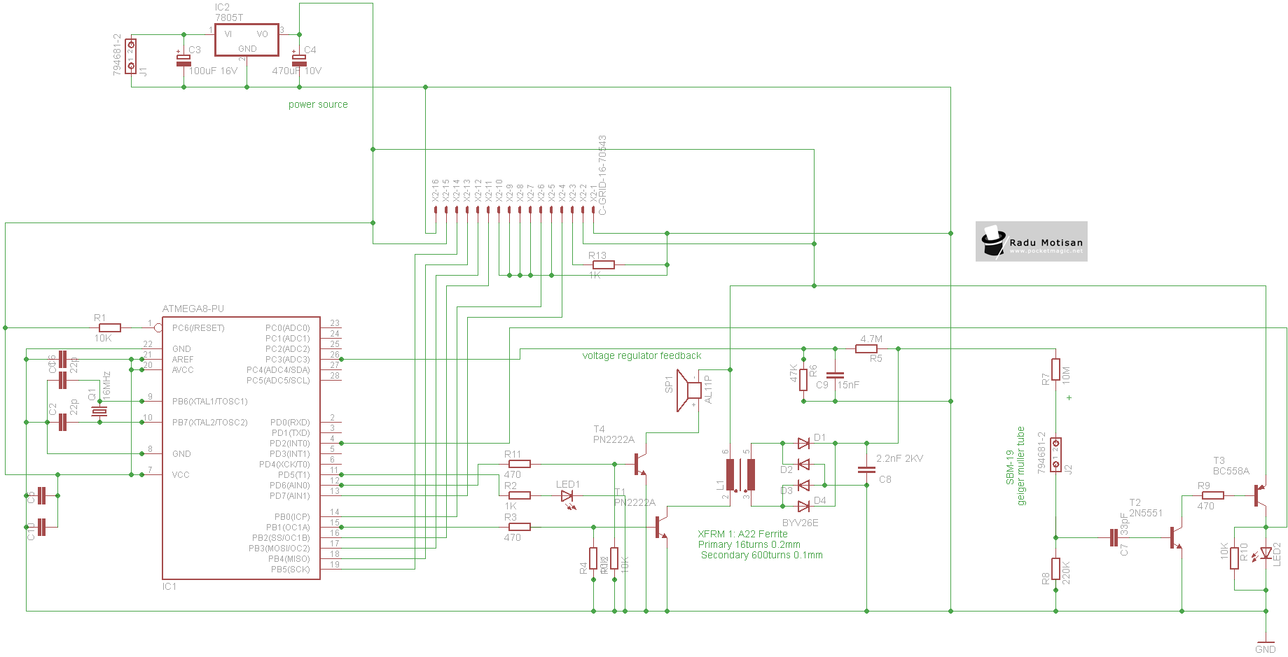
An efficient and stable construction for radiation dosimetry needs. The design centers around the Atmel Atmega8 microcontroller and a Russian Geiger Muller tube, specifically the CTC-1 tube for high gamma doses. The dosimeter is compatible with various tubes including...
A simple oscillator that can be utilized for code practice. To achieve adequate inductance for generating an audio frequency, an iron core transformer, similar to those employed in audio transformer-coupled amplifiers, is connected as illustrated. The circuit comprises a basic...
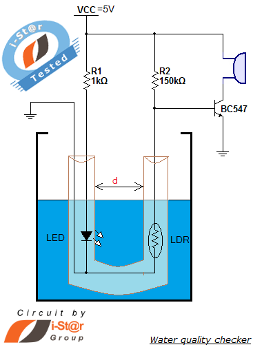
How to measure water purity and test water quality using a simple electronics project. Water purity measurement and water quality analysis can be performed using a water purity checker circuit. This circuit is constructed around a Light Dependent Resistor...