
BH1417F FM stereo transmitter electronic project

The BH1417F FM stereo transmitter circuit is designed to facilitate the effective transmission of audio signals over short distances using frequency modulation. The core component, the BH1417F IC, integrates both the stereo modulation and transmission functionalities, allowing for efficient signal processing and broadcasting. The stereo modulator within the IC generates a composite audio signal by combining the left (MAIN) and right (SUB) audio channels, along with a pilot tone at 19 kHz, which is essential for demodulating the stereo signal at the receiver end.
The oscillator circuit operates at 38 kHz, which is critical for the generation of the pilot tone and for maintaining the integrity of the stereo signal. This ensures that the receiver can accurately reconstruct the audio channels, providing a high-fidelity listening experience. The design of the L1 coil is important for the tuning and stability of the transmitter. The specified coil, constructed with 2.5 turns of enameled copper wire, contributes to the resonant characteristics necessary for efficient signal transmission. The inclusion of a ferrite slug allows for tuning adjustments, enhancing the circuit's performance.
This circuit is particularly advantageous for applications such as personal broadcasting, where users wish to transmit audio content from portable devices to nearby FM receivers. Its range of approximately 20 meters makes it suitable for home use, events, or demonstrations, where audio signals need to be shared without the constraints of wired connections. Overall, the BH1417F FM stereo modulator circuit represents a practical solution for wireless audio transmission, combining simplicity in design with effective performance.This stereo FM stereo modulator circuit use the BH1417F FM stereo transmitter IC which consists of a stereo modulator for generating stereo composite signals and a FM transmitter for broadcasting a FM signal on the air. The stereo modulator generates a composite signal which consists of the MAIN, SUB, and pilot signal from a 38kHz oscillator.
This BH1417F stereo FM transmitter is capable of broadcasting good quality signals over a range of about 20 meters and is ideal for broadcasting music from a CD player or from any other signal source so that it can be picked up in another location. L1 coil comprises 2. 5 turns of 0. 5 - 1mm enamelled copper wire (ECW) wound onto a tapped coil former fitted with an F29 ferrite slug. Alternatively, you may also use any commercially made 2. 5 turns variable coil. 🔗 External reference
Related Circuits
Integrated circuits (ICs) that were once prohibitively expensive for hobbyists are now more affordably priced. A notable example is the AD8099 from Analog Devices, which is available for a modest cost. The AD8099 is a high-speed operational amplifier (op-amp)...
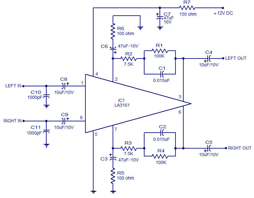
The LA3161 is an integrated two-channel preamplifier designed for car stereo applications. It operates on a 12V DC power supply. The LA3161 preamplifier is specifically engineered to enhance audio signals in automotive environments, ensuring optimal sound quality for car stereo...
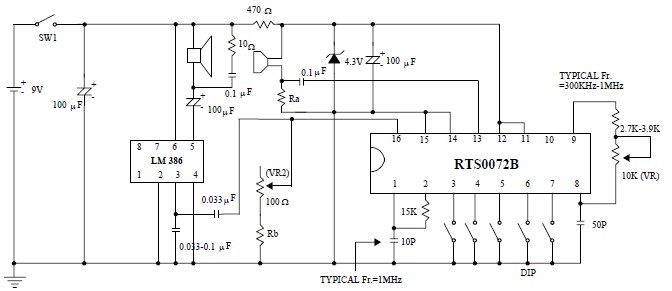
This voice changer circuit diagram is an electronic project developed using the RTS0072B single-chip CMOS LSI, specifically designed for voice-changing applications. It can transpose or distort one voice into another by encoding the input audio signals at normal speed...
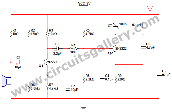
This is a simple 2N2222 transistor-based FM transmitter circuit that operates within the FCC (Federal Communications Commission) limits, meaning no license is required for its use. FM stands for Frequency Modulation, which is a method of transmitting radio frequency...
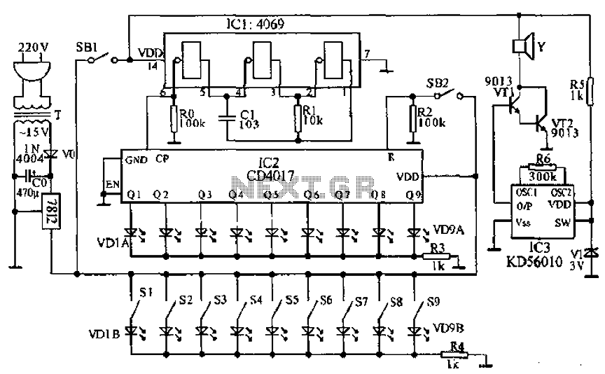
This document presents a principle circuit for electronic games. The main circuit operates in conjunction with the host through the reset button SB2, while the indicators VD1A-VD9A remain off. Prizes, for example, five, are determined by the number of...
The FM302E-I-type FM transmitter exciter is manufactured by NEC Corporation, Japan, and features a 1210 motherboard. It utilizes direct frequency modulation of the carrier signal, employing phase-locked frequency stabilization and frequency synthesis techniques. The front power amplifier is based...