
Simple short range portable FM transmitter circuit diagram

The 2N2222 transistor-based FM transmitter circuit is designed for efficient audio transmission while adhering to regulatory guidelines. The circuit architecture includes a condenser microphone that captures audio signals, which are then processed through a coupling capacitor (C1) to ensure that only the AC component of the audio signal is passed forward while blocking any DC bias. The pre-amplifier stage, facilitated by the 2N2222 transistor (Q1), amplifies the audio signal, making it suitable for further processing.
The biasing resistors (R2 and R6) are crucial for establishing the operating point of the transistor Q1, ensuring it remains in the active region for optimal amplification. The amplified output from the collector of Q1 is then fed into the base of the second transistor (Q2) through capacitor C3, which serves to isolate the audio signal from the DC biasing of Q2, preventing distortion.
Transistor Q2, along with variable capacitor C7 and an inductor, forms the core of the RF oscillator circuit. This configuration allows for the generation of RF signals in the 80 to 130 MHz range, which is suitable for FM transmission. The variable capacitor C7 is key for tuning the oscillator to the desired frequency, enabling the circuit to adapt to different transmission requirements.
The overall design emphasizes simplicity and portability, making it ideal for various applications such as vehicle FM transmitters, walkie-talkies, and wireless audio systems. The range of approximately 120 meters provides sufficient coverage for personal use, while the frequency modulation technique ensures that the transmitted audio maintains clarity and fidelity when received by standard FM radios. The design adheres to FCC regulations, making it accessible for hobbyists and professionals alike, without the need for licensing.This is a simple 2N2222 transistor based radio FM transmitter circuit within the FCC (Federal Communications Commission) limit, that is no license is necessary for using thisstable FM transmitter circuit. What is an FM transmitter FM stands for Frequency Modulation andFM transmitter is a radio frequency (RF) transmitter which uses frequency modul
ation of audio signals. Frequency modulation means that the frequency of a carrier signal is changed according to the input audio signal. The portable FM transmitteris able to transmit sound or music to any standard radio FM receiver. The range of this transmitter is near to 120 meters. Audio signal is applied via a condenser micro phone, which is a capacitive sound sensor. Simplicity and portability makes this transmitter circuit superior to other FM transmitters. The transmission frequency of this FM transmitter can be adjusted using the variable capacitor C7. The main applications of this circuit includesFM transmitter for car, walky talky, wireless audio transmitteretc.
The signal from the condenser microphone is passed through a coupling capacitor C1 and amplified by transistor Q1, which acts as a pre amplifier. The amplified signal is applied to the base of transistor Q2. R2 and R6 provide necessary biasing to the amplifier transistor Q1 (2N2222). Amplified sound signal will be available at the collector of Q1 and it coupled to the base terminal of transistor Q2 via the capacitor C3 and R4.
Q2, C7 and the inductor forms a RF oscillator circuit that operates in the 80 to 130 MHz range, which is voltage controlled oscillator so its frequency can be modulated by the input audio signal. 🔗 External reference
Related Circuits
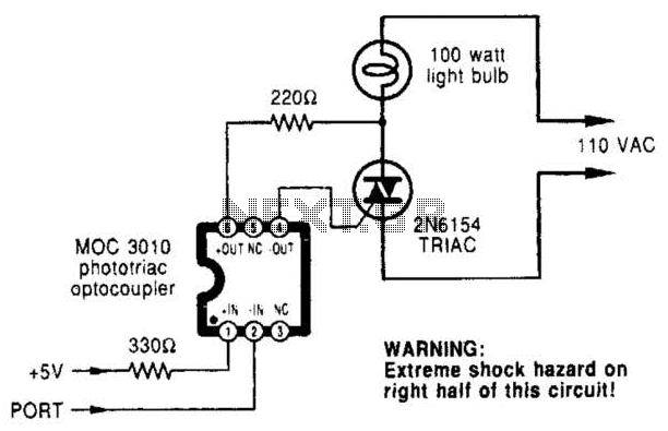
A microcomputer-to-triac interface utilizes a phototriac optoisolator to safely isolate logic signals, allowing direct control of high-power loads. This circuit can function as either an on/off switch or a proportional phase control, depending on the input waveforms and the...
This schematic represents an FM transmitter capable of delivering an output power of 3 to 3.5 W, operating within a frequency range of 90 to 110 MHz. While the stability of the circuit is acceptable, the integration of a...
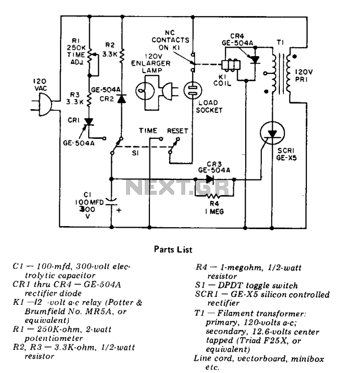
This precision solid-state time delay circuit features both delayed off and delayed on switch functions, which can be interchanged by simply swapping the relay contacts. The described time delay circuit is designed to provide precise control over the timing of...
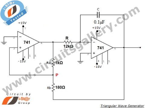
An operational amplifier-based triangular waveform generator is a simple circuit that is widely used in function generators. This circuit utilizes the 741 operational amplifier to create a triangular wave generator. The output waveform of an integrator will be triangular...
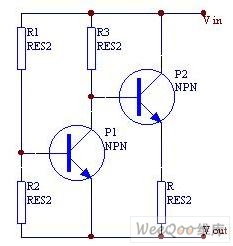
When the current is below the specified threshold, the bias current supplied by resistor R1 causes transistor P3 to saturate and conduct. In this state, it is unable to regulate the current effectively. Conversely, when the current reaches or...
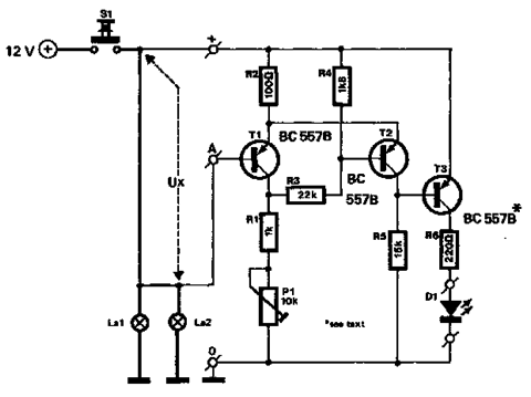
The circuit described below monitors the car's brake lights and indicates their operational status using a 12V light-emitting diode (LED). This functionality can prevent fines for driving with defective brake lights and enhance road safety. The monitor relies on...