
bi directional level shifter

In electronic design, the integration of devices operating at different voltage levels necessitates careful consideration of signal integrity and compatibility. The bi-directional level shifter serves as a critical component in such mixed-voltage environments. The 2N7000 MOSFET, a widely available N-channel MOSFET, is utilized due to its favorable characteristics, including low on-resistance and sufficient switching speed for most digital applications. The configuration involves connecting the gate of the MOSFET to the lower voltage side, which allows the MOSFET to turn on when the higher voltage signal is present, effectively passing the signal through to the lower voltage side.
The choice of 10K resistors on both sides of the level shifter aids in providing a balanced pull-up configuration, which is particularly beneficial for serial communication protocols. This resistor value is a common standard that ensures reliable signal levels without excessive power consumption. For I2C communication, where pull-up resistors are essential for proper operation, the specified values of 4.7K and 3.3K must be adhered to for the respective voltage levels. This configuration guarantees that the I2C bus can operate correctly, allowing for reliable data transmission between devices.
When designing circuits that incorporate level shifting, it is crucial to avoid duplicating pull-up resistors on the same signal line, as this can lead to contention and signal degradation. Proper circuit layout and component selection are paramount to ensure that the level shifter functions as intended, maintaining the integrity of the signals being transmitted across different voltage domains. This approach not only enhances the versatility of the circuit design but also facilitates the integration of a diverse range of electronic components.On your circuit 5v was the most common voltage for electronic components, everything was 5v, and a lot still is now. USB is still a 5v protocol, and many microcontrollers are still 5v. As electronics have become more efficient and smaller however, their power consumption has also gone down, so now we see many 3.
3v devices. The trouble is that often there is now a mixture of these different voltage levels on a circuit, so when different voltage devices want to communicate signals need to be stepped down with resistors. This was fine, as generally it was the 5v microcontroller having its output voltage stepped down to a lower voltage, but there were issues.
Resistor solutions work one way, i. e. when you need to lower the voltage level of a signal. But when the problem is reversed such that the voltage of your signal is not enough to trigger an input so that you need to step it up, then resistors are no good. The solution to stepping down and stepping up a voltage is to use a Bi-directional level shifter. I used the general purpose 2N7000 MOSFET, but I had used some 3A power MOSFET`s while I was waiting for the 2N7000`s to arrive!
Note that the Gate is always connected to the LOWER voltage. Any devices that share a signal line but are on two different voltages can use this set up. The 10K resistors on either side, I have found to work well with serial data. Another application of a level shifter would be with two I2C devices working on different voltages. The resistors would then take the values of the corresponding pull-up resistor for the I2C line, usually 4. 7K on the 5v side and 3. 3K on the 3. 3v side; this will provide a suitable current of 1mA. Be careful here, don`t have two sets of pull-up resistors on the same line, if you already have them installed somewhere else then don`t include them again.
🔗 External reference
Related Circuits
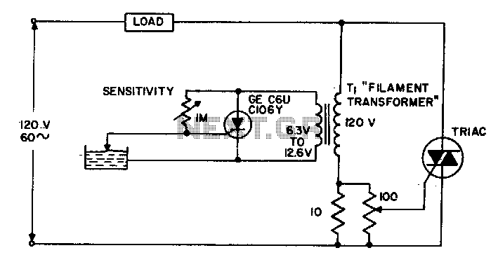
The circuit supplies power to the load until water conducts through the probe, allowing gate current to bypass from the low current SCR. This configuration provides an isolated low voltage probe to meet safety requirements. The described circuit operates as...
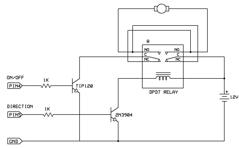
One of the simplest methods to enable a motor to rotate in both directions is by utilizing a double-pole, double-throw (DPDT) relay. This setup requires two transistors and two Stamp pins: one for on/off control and the other for...
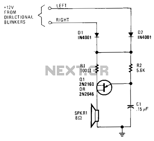
A unijunction transistor audio oscillator drives a small speaker. The oscillator's frequency is determined by resistor R2 and capacitor C2. The operating voltage is supplied from the car's turn-signal circuit(s) through D1 and D2. The diodes conduct current from...
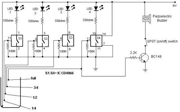
A low-cost water level indicator circuit can be designed using this schematic. This water level indicator utilizes a CMOS IC, the CD4066, to indicate the amount of water present in an overhead tank and provides an alarm when the...
R1 = 470K, N1, N2 = MC14093B, R2 = 15M, T1 = 2N3906 (also compatible: PN200, 2N4413), C1-C4 = 2.2nF (NTE159, ECG159, BC557, BC157, TUP), D1 = 1N4001, Ry = Relay (12V or matching supply voltage), D2, D3 =...
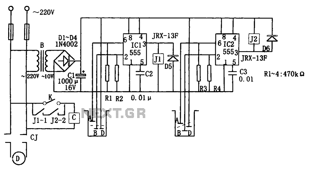
The level control circuit comprises a step-down rectifier circuit, a trigger circuit utilizing two 555 timer ICs (IC1 and IC2), and a relay control circuit. The rectifier circuit is responsible for providing the necessary DC voltage for the flip-flop...