
water level indicator circuit using cmos ics

The water level indicator circuit employs a CMOS IC CD4066, which functions as a quad bilateral switch, allowing for the control of multiple indicators based on water level changes. The circuit is designed with a series of resistors and LEDs that visually represent the water level in the tank. The 180K resistor plays a crucial role in ensuring that when the water level is low, the circuit remains inactive, keeping the LEDs off.
As water enters the tank, it creates a conductive path between the wire connected to switch S1 and the positive supply. This action closes switch S1, allowing current to flow and illuminating LED1, which indicates the initial water level. As the water continues to rise, additional wires connected to subsequent switches (S2, S3, and S4) are shorted, sequentially lighting up LEDs 2, 3, and 4, thus providing a clear visual indication of the water level.
The circuit also incorporates a BC148 transistor, which acts as a switch for the buzzer. When the water level reaches its maximum height, it pulls the base of the BC148 high, causing the transistor to saturate. This saturation allows current to flow through the buzzer, activating it and providing an audible alarm to signal that the tank is full. To deactivate the buzzer, the user must open the SPST switch, which interrupts the circuit and stops the buzzer from sounding.
This design is advantageous due to its simplicity, low cost, and effectiveness in providing both visual and audible alerts for water level management in overhead tanks. The use of a CMOS IC ensures low power consumption, making the circuit suitable for continuous operation in various applications.A very simple low cost water level indicator circuit can be designed using this schematic circuit. This water level indicator is based on a simple CMOS IC CD4066 and indicates the amount of water present in the overhead tank and also gives an alarm when the tank is full. When the water is empty the wires in the tank are open circuited and the 180 K resistors pulls the switch low hence opening the switch and LEDs are OFF. As the water starts filling up, first the wire in the tank connected to S1 and the + supply are shorted by water. This closes the switch S1 and turns the LED1 ON. As the water continues to fill the tank, the LEDs2, 3 and 4 light up gradually. When the water is full, the base of the transistor BC148 is pulled high by the water and this saturates the transistor, turning the buzzer ON.
The SPST switch has to be opened to turn the buzzer OFF. 🔗 External reference
Related Circuits
A real-time controller is a device designed to continuously manage household devices, both in real-time and according to a predetermined schedule. This article focuses on a series of real-time controllers utilizing the AT89C2051 microcontroller, which serves this purpose effectively....
This circuit provides a digital square wave that can be viewed directly or used to drive other circuits. It used the CMOS 4047 Low-Power Monostable/Astable Multivibrator. As used in Tom Duncan's Adventures with Digital Electronics Book, to drive CMOS...
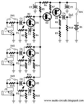
The following circuit illustrates a Mini Audio Mixer with Level Control Circuits. Features include switchable high/low sensitivity, providing high performance. The Mini Audio Mixer circuit is designed to facilitate the mixing of multiple audio signals while allowing for level control...
This circuit automatically activates and deactivates a motorcycle's headlight, functioning independently of both the light and ignition switches, as long as the battery is fully charged. The initial stage employs a 220-ohm resistor and ZD1 to keep transistor Q1...
This document does not aim to provide an extensive account of the integrated circuits (ICs) used in this circuit. For additional information on this topic, please refer to the "Flip-Flop Made With A LM556 Timer Chip" section and the...
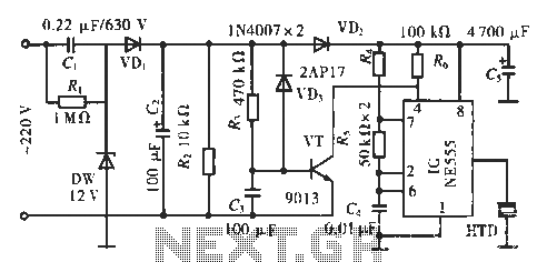
The circuit utilizes a 555 integrated circuit (IC). When an incoming call is received, 220 V AC is stepped down through resistor R1, followed by rectification using diode VD1. A voltage regulator (DW) is employed, and capacitor C2 is...