
Bi-Directional Telephone Line

The described project implements a telephone line simulation circuit that effectively emulates the essential functionalities of a traditional telephone system. The central component of the circuit is a 555 timer configured in astable mode, which generates a continuous square wave signal. This signal serves as the clock for the cascaded binary counters, which are typically 4-bit or 8-bit counters. These counters are responsible for producing various output frequencies corresponding to different telephone tones, such as dial tones and ringing signals.
The outputs from the counters are fed into operational amplifiers that are configured to detect the on-hook and off-hook states of the connected telephone devices. The first pair of operational amplifiers monitors the voltage levels to determine whether the phones are active or idle. This is essential for simulating the real-world behavior of telephone lines, where the state of the phone significantly affects the circuit's operation.
To simulate the ringing of a telephone, a third operational amplifier is employed to monitor the ringing current. This current is indicative of an incoming call, and the op-amp's output can be used to activate the ringing signal circuit. The ringing signal is generated using discrete components that perform voltage multiplication and convert the DC voltage to an AC waveform, mimicking the ringing voltage typically found in telephone systems.
Event storage and control of the signal flow within the circuit are managed by R/S latches and logic gates. These digital components allow the circuit to remember previous states and manage transitions between different operational modes, such as switching from a ringing state to an active call state.
The final stage of the circuit involves the use of miniature relays that act as switches to connect or disconnect the simulated line. When a call is initiated, the relays are activated to establish a connection between the two telephone devices. Conversely, when a call is incoming, the relays can switch to a ringing configuration, allowing the simulated phones to ring until answered.
Overall, this project provides a cost-effective solution for simulating telephone interactions, making it a valuable tool for educational purposes or for hobbyists interested in telecommunications and electronics.This self-build project can simulate a telephone call / connection between any two local telephone devices. This for a fraction of the outlay of some commercial units, many with cost-increasing features that usually are not required.
The circuit is centred on two cascaded binary counters clocked by a 555 astable multivibrator. Several of the counters` outputs provide the frequencies, tones and time delays required. A pair of operational amplifiers detect on / off hook conditions at both ends of the simulated line. To detect call answering, a third op-amp monitors the ringing current. R/S latches and logic gates provide event storage and signal control. Discrete circuits provide the voltage multiplication and DC to AC conversion required for the ringing signal. A pair of miniature relays, switch each end of the simulated line between connection and ringing. 🔗 External reference
Related Circuits
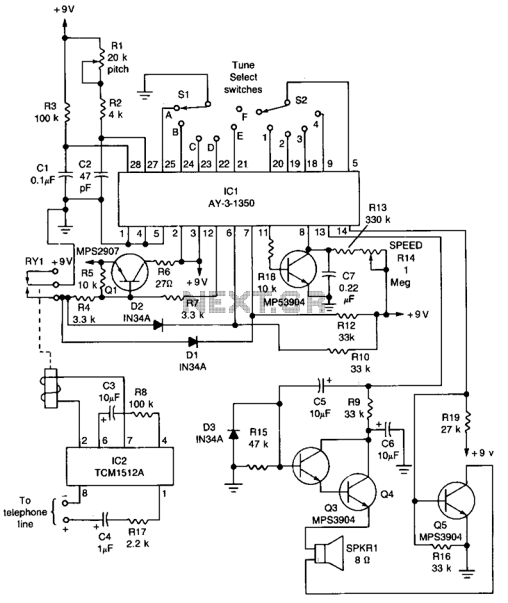
The core component of the circuit is IC1, the AY-3-1350 melody synthesizer IC from General Instrument. IC2 is a TCM1512 telephone ring detector IC powered by the telephone line. The circuit operates when IC2 detects a ring pulse on...
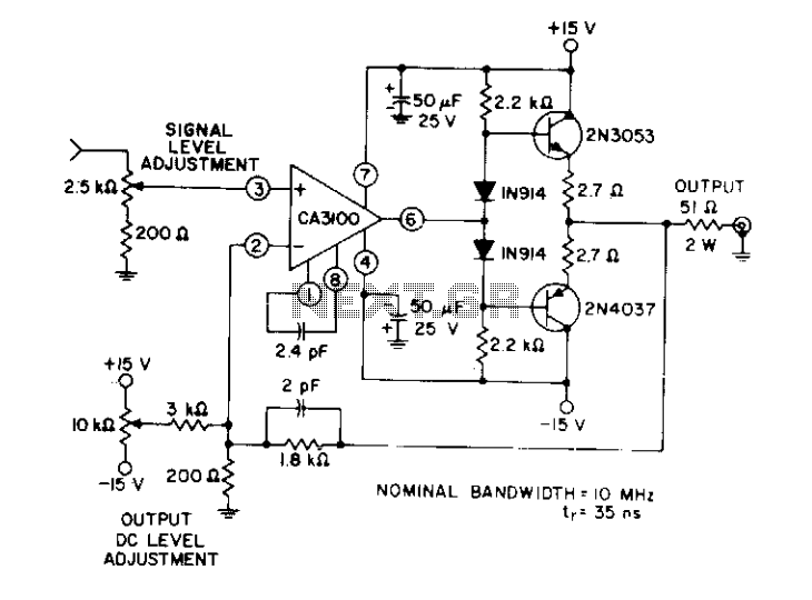
This circuit utilizes a wideband, high slew rate CA3100 BiMOS operational amplifier. The slew rate for this amplifier is 28 V/µs. The output swing is 9 volts peak-to-peak into a terminated line, measured at the termination. The CA3100 BiMOS operational...
Alkaline Battery Charger. This circuit was specifically designed to recharge alkaline cells. The unusual connection of the transistor in each charging unit will cause it to oscillate. The alkaline battery charger circuit is engineered to effectively recharge alkaline batteries, which...
A smart card is designed using EEPROM chips, while smart card readers utilize a Renesas microcontroller. The card reader reads data from the smart card and transmits it to a computer via its serial port. Access is granted only...
If the sensor system requires an active supply, a single pair of cables can be utilized to transmit both the power supply and the output signal. This approach simplifies the overall system. In sensor systems that necessitate an active power...
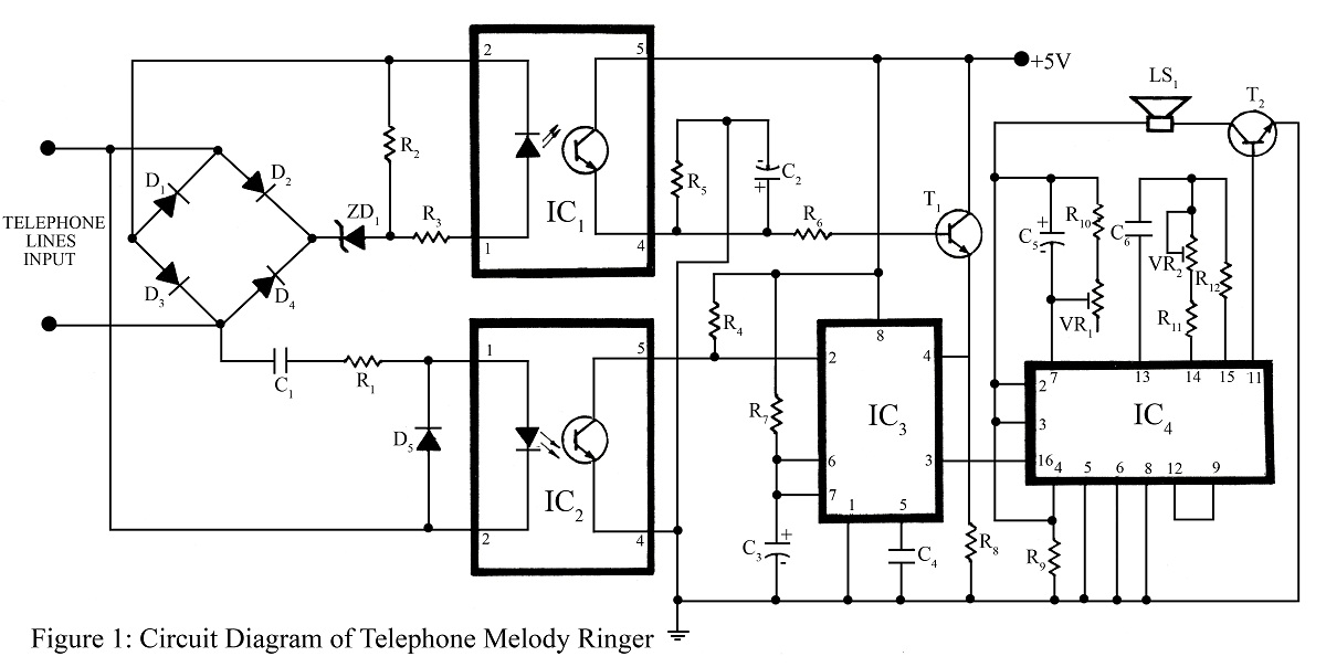
The telephone project described here is a telephone ringer that produces pleasant tunes when a call is received. The tunes generated by this telephone ringer are more melodious and soothing compared to those of traditional telephone instruments and piezo...