
Alkaline Battery Charger

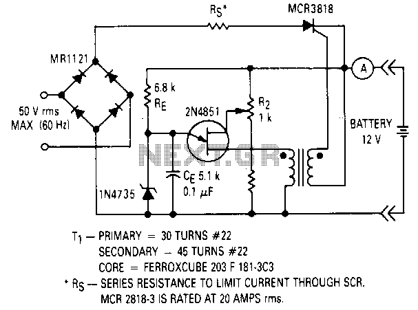
The alkaline battery charger circuit is engineered to effectively recharge alkaline batteries, which typically require a specialized approach due to their unique chemistry. The primary components of this circuit include a power supply, a charging control unit, and a feedback mechanism involving a transistor that oscillates to regulate the charging process.
The circuit operates by converting the AC voltage from the power supply into a suitable DC voltage for charging the batteries. The transistor's unconventional configuration plays a crucial role in this process. It is connected in such a way that it creates an oscillating signal, which is essential for maintaining a consistent charging current. This oscillation helps prevent overheating and overcharging, which can damage alkaline cells.
Additionally, the circuit may include resistors and capacitors that work together to filter the output and stabilize the voltage. A diode is also typically included to prevent reverse current flow, ensuring that the batteries are charged efficiently and safely. The design may incorporate an LED indicator to signal the charging status, providing visual feedback to the user.
Overall, this alkaline battery charger circuit is a specialized solution that addresses the unique requirements of charging alkaline batteries, ensuring longevity and safety during the charging process.Alkaline Battery Charger, Battery Charger , This circuit was specifically designed to recharge alkaline cells. The unusual connection of the transistor in each charging unit will cause it to osci. 🔗 External reference
Related Circuits
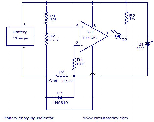
This simple circuit can be used to monitor whether a battery is charging. The voltage comparator IC LM393 is the core component of this circuit. The LED D1 will remain ON whenever there is at least 25 milliampere current...
A constant-voltage active load can function as a battery during the charge cycle. The load voltage can be adjusted from 5 to 35V using potentiometer PV, simulating batteries with voltages ranging from 6 to 32V. In the testing of...
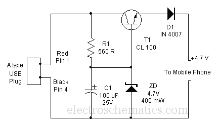
A mobile phone can be charged using the USB outlet of a PC. This simple USB cellphone charger circuit provides a regulated output of 4.7 volts for charging the mobile phone. The USB outlet typically supplies 5 volts DC...
This simple charger utilizes a single transistor as a constant current source. The voltage across a pair of 1N4148 diodes biases the base of the BD140 medium power transistor. The base-emitter voltage of the transistor and the forward voltage...
This circuit will not function unless the battery to be charged is connected with the correct polarity. The voltage of the battery regulates the charger, and when the battery is fully charged, the charger will stop supplying current to...
The charger design is akin to many commercially available chargers. It comprises a mains adapter, two resistors, and a light-emitting diode (LED). In practical applications, this type of charger functions effectively. Resistor R1 serves dual purposes: it sets the...