
bicycle back safety light

The circuit operates at a low voltage, typically around 3V, making it suitable for battery operation. The use of high-efficiency LEDs ensures that the device consumes minimal power, extending battery life, which is particularly beneficial for outdoor applications such as cycling and jogging. The configuration of the LEDs in two series allows for an engaging visual effect that enhances visibility during low-light conditions.
The astable multivibrator configuration of the 555 IC is crucial for generating the flashing effect. It produces a square wave signal that alternates between high and low states, effectively controlling the LEDs' on and off states. The first set of LEDs (D1-D6) is connected directly to the positive supply rail, allowing them to flash in synchrony with the output of the first 555 IC. Meanwhile, the second 555 IC serves to trigger and invert the signal for the second set of LEDs (D7-D12), creating the alternating flashing pattern that simulates a rotating light.
The inclusion of the permanently lit LED (D13) at the center serves both a functional and aesthetic purpose, providing a constant point of illumination that enhances the overall visibility of the device. This design choice is particularly advantageous for safety applications, ensuring that the device remains noticeable even when the flashing LEDs are not active.
Overall, the circuit's thoughtful design, combining efficient components and strategic layout, results in a reliable and visually appealing lighting solution suitable for various outdoor activities.This circuit has been designed to provide a clearly visible light, formed by 13 high efficiency flashing LEDs arranged in a pseudo-rotating order. Due to low voltage, low drain battery operation and small size, the device is suitable for mounting on bicycles as a back light, or to put on by jogger/walkers.
IC1 is a CMos version of the 555 IC wired as an astable multivibrator generating a 50% duty-cycle square wave at about 4Hz frequency. At 3V supply, 555 output (pin 3) sinking current operation is far better than sourcing, then LEDs D1-D6 are connected to the positive supply rail. In order to obtain an alternate flashing operation, a second 555 IC is provided, acting as a trigger plus inverter and driving LEDs D7-D12.
D13 is permanently on. The LEDs are arranged in a two series display as shown below, with a center LED permanently on. This arrangement and the alternate flashing of the two series of LEDs provide a pseudo-rotating appearance. 🔗 External reference
Related Circuits

This circuit generates a pulse when an object on the conveyor belt obstructs the light source. The light source continuously keeps the phototransistor activated, resulting in a high logic level voltage at the Schmitt-trigger inverter and a TTL-compatible low...

The power windows operate slowly, but connecting 12 volts directly to the motors allows them to function properly. A previous discussion mentioned using a common 5-pin ice cube relay, but there was no confirmation of its effectiveness. The power...

This design utilizes standard metal gate CMOS logic rather than the typical PIC or custom chip. A 22µF capacitor charges during one half of the AC cycle and provides trigger current to the triac during both halves. The circuit employs...

This white LED floodlight illuminates your porch with cool white light. The circuit features a simple and energy-saving design, with a low current consumption. The LED floodlight circuit typically consists of a power supply, a control circuit, and the LED...
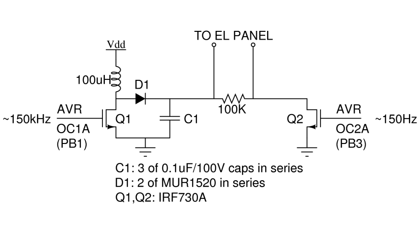
There are two primary types of backlights for LCDs: LEDs, which stands for light-emitting diodes, and EL, which stands for electroluminescent. EL backlights are generally more efficient and provide more uniform lighting compared to LED backlights, but they require...
This is an audio-controlled lamp circuit. This circuit requires a low voltage input, such as from pre-amplifiers, tone control, or general audio line level output. The audio-controlled lamp circuit is designed to activate a lamp in response to audio signals....