
Audio-Controlled Incandescent Lamp Light Controller

The audio-controlled lamp circuit is designed to activate a lamp in response to audio signals. The circuit typically operates at low voltage levels, making it suitable for integration with various audio sources, including pre-amplifiers and tone control units.
The core of the circuit consists of a microphone or audio input stage that captures sound waves and converts them into electrical signals. These signals are then processed by a signal conditioning stage, which may include filtering and amplification to ensure that the audio input is within the appropriate range for triggering the lamp.
A comparator circuit is often used to analyze the amplitude of the audio signal. When the audio signal exceeds a predefined threshold, the comparator output changes state, activating a transistor or a relay that controls the lamp's power supply. This allows the lamp to turn on or off based on the intensity of the incoming audio signals.
Additionally, the circuit can include features such as adjustable sensitivity to accommodate different audio levels and environments. A potentiometer may be incorporated into the design to allow users to set the threshold level according to their specific needs.
For safety and reliability, it is essential to ensure that the circuit is designed to handle the power requirements of the lamp being controlled. This may involve selecting appropriate components, such as transistors with adequate current ratings or relays that can manage the lamp's voltage and current specifications.
In summary, the audio-controlled lamp circuit serves as an innovative solution for creating interactive lighting effects based on audio inputs, enhancing both functionality and ambiance in various applications.This is a audio-controlled lamp circuit. This circuit requires low voltage input such as pre-amplifiers, tone control, or general audio line level output. It`s. 🔗 External reference
Related Circuits
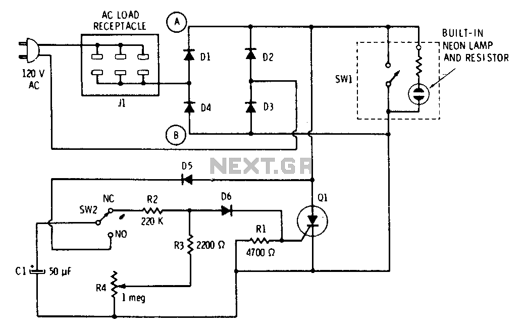
The push button and potentiometer initiate a time delay that turns a light on and then automatically turns it off again after a predetermined time. The potentiometer can be set for a delay of a few seconds to just...

A simple frequency meter or frequency counter circuit featuring an LCD display and an AVR microcontroller. This includes a DIY schematic circuit diagram and embedded C code. The frequency meter circuit is designed to measure the frequency of input signals...
This bulletin outlines the applications, design features, equipment arrangement, and space planning for the type 230 controllers. These controllers are designed for the control and protection of induction motors or transformers in 2300-4160 volt systems. Each type 230 controller...
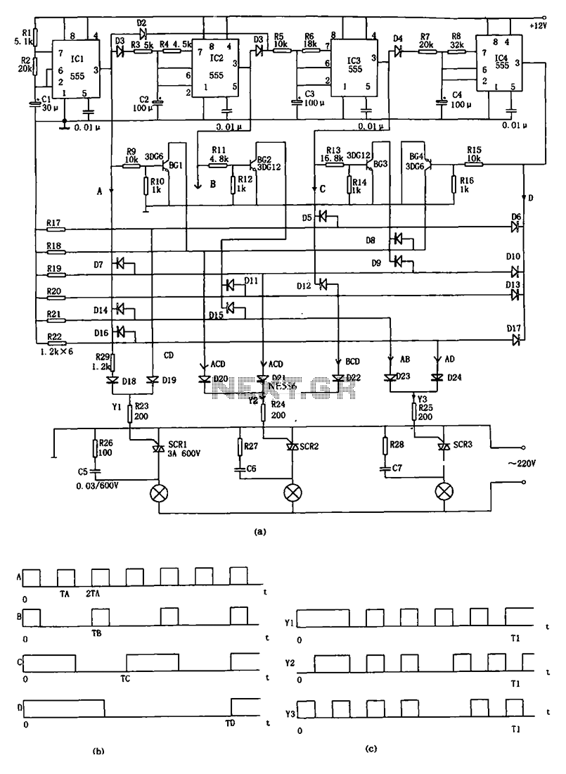
The decorative lamp control circuit is illustrated in the figure. The controller comprises a pulse generator, a frequency divider, a matrix circuit, and a thyristor control circuit. Components IC1, R1, R2, C1, and others form a multivibrator where the...
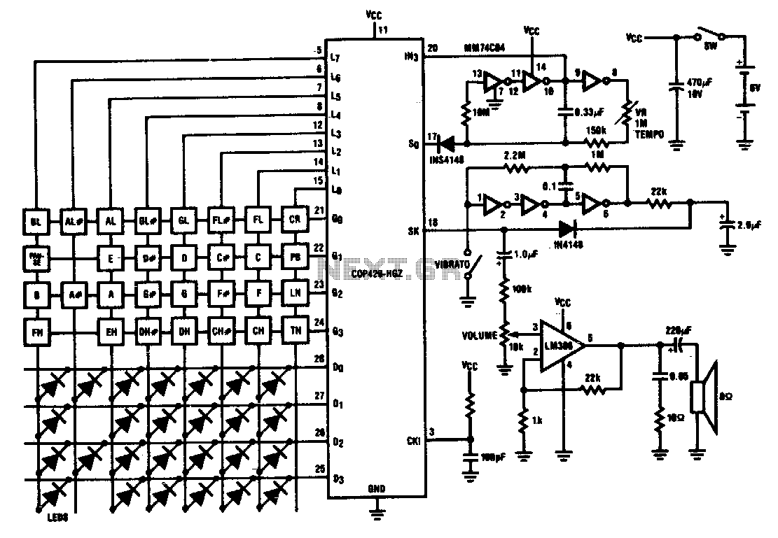
Twenty-five musical keys and 25 LEDs are provided to denote F to F" with half notes in between. Memory can store a played tune. There are ten preprogrammed tunes (each has an average of 55 notes) masked in the...
A 40-watt fluorescent tube lamp or two 20-watt tubes in series will be driven by this circuit. The transformer is wound on a ferrite rod with a diameter of 10 mm and a length of 8 cm. The circuit described...