
bicycle generator circuit

The voltmeter scale modification process involves several steps to ensure accuracy and aesthetics. Initially, the old scale must be carefully removed to avoid damaging the underlying components of the voltmeter. Once the scale is scanned, it is essential to maintain the original scale's proportions and alignment to ensure that the new markings correspond accurately to the voltage readings.
Using graphics editing software allows for precise adjustments, such as resizing and rotating the new voltage numbers. When adding new markings, attention to detail is crucial to ensure that they are not only visually aligned but also spaced correctly to maintain readability. The choice of printing on photo-quality paper enhances the clarity and durability of the new scale, ensuring that it withstands regular use.
For those opting for a CAD program, this method provides the advantage of designing a completely new scale tailored to specific requirements. The use of Lazertran transfer paper allows for high-resolution printing, which can be transferred onto the original scale, providing a seamless integration of the new design. The underlying white spray paint serves as a neutral background, enhancing the visibility of the new markings.
Overall, this process allows for the effective customization of voltmeter scales, improving both functionality and visual appeal while ensuring that the instrument remains accurate and reliable for voltage measurements.The original scale on my voltmeter was from 0 to 30volts. I made a new scale by removing the old scale from the meter and scanning it into a paint package on my PC. I deleted the old numbers but left the scale in tact. I then just added my new numbers on the volts scale and rotated them to match. This was then printed on photo quality paper cut ou t and spray mounted to the old scale. You could also use a Cad program to draw the scale from scratch and print onto lazertran transfer paper and transfer onto the original scale spray painted white. 🔗 External reference
Related Circuits

A simple motor control project for forward and backward drive can be implemented using the LB1948M motor driver IC, which features two channels for motor control. The LB1948M is an ideal choice for 12V motor drive systems and can...

In this TMOS pulser, a negative-going pulse is applied to U1, a high-speed CMOS buffer, which directly drives the gate of Q1, an MTP3N35. If only a 100-V pulse is required, the MTA6N10 can be used. The pulse output...
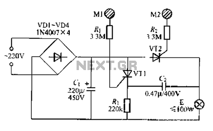
A circuit configuration features a relatively new strong key touch-state switch. Normally, the thyristors VT1 and VT2 are in the off-state, allowing minimal current to pass through the lamp F. At this point, the capacitance C comes into play....

Electronic FM Telephone Transmitter Schematic. The following schematic design illustrates a circuit diagram for an FM telephone transmitter built on a compact PC board layout. This small design allows it to be easily integrated within the housing of a...

Intercom walkie-talkies represent an advanced application of crystal oscillators for voice transmission. Utilizing a crystal-locked oscillator for voice transmission is complex due to the oscillator's fixed frequency, which is challenging to modulate. The primary method for achieving this involves...
This circuit demonstrates how a low-drift preamplifier can enhance the measurement resolution of a thermocouple. The preamplifier is powered by the reference regulator, and bridge feedback is employed to bias the preamplifier input within its common mode range. Cold...