
Schematic Diagram Electronic FM Telephone Transmitter Circuit

The FM telephone transmitter circuit operates by modulating the audio signals from a telephone line onto a carrier frequency suitable for FM transmission. Key components of the circuit typically include a microphone, an operational amplifier, a voltage-controlled oscillator (VCO), and a radio frequency (RF) amplifier.
The microphone captures audio signals from the telephone conversation, which are then amplified by the operational amplifier to ensure sufficient signal strength. The VCO modulates the amplified audio signal onto a specific frequency, effectively converting the audio into an FM signal. The RF amplifier further boosts this signal, allowing it to be transmitted over a short distance.
Power for the circuit is derived directly from the telephone line, which eliminates the need for an external power source. This feature not only simplifies the design but also enhances the portability of the device. The compact nature of the PC board layout allows for seamless integration into the telephone housing, maintaining the aesthetic and functional integrity of the device while providing added capabilities.
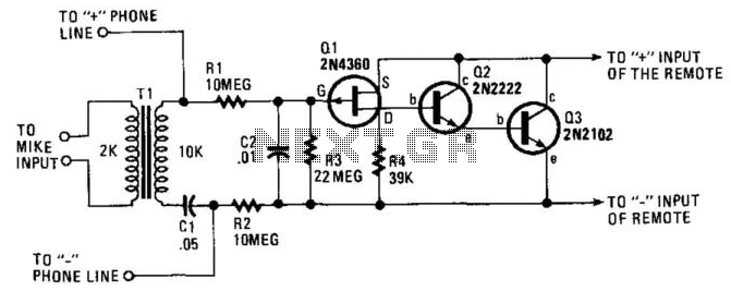
Careful consideration is required in the design to ensure that the circuit does not interfere with the normal operation of the telephone line. Additionally, the circuit must comply with relevant regulations governing the transmission of radio frequencies to avoid legal issues. Proper shielding and filtering techniques may be implemented to minimize unwanted emissions and ensure that the device operates within designated frequency bands.Electronic FM Telephone Transmitter SchematicThe following schematics design pictures is a circuit diagram FM telephone transmitter that built on a PC board layout which is so small it can simply be fitted within the housing of a telephone creating it an instant pseudo-speak earphone. This circuit diagram FM telephone transmitter components connec ts in series with telephone line, steals power 🔗 External reference
Related Circuits
The 555 timer is recognized as one of the most versatile and widely used integrated circuits globally. One of its potential applications is as a simple inverting Schmitt trigger. The 555 timer can be configured in various modes, including monostable,...
Today, nearly all computers are equipped with logic blocks designed to implement a USB port. In practice, a USB port can deliver over 100 mA of continuous current at 5V to the peripherals connected to the bus. This capability...

The adjustment potentiometer for the Raspberry Pi can modify the conduction angle of the thyristor VI and V2, which in turn adjusts the speed of the DC motor M. The speed feedback circuit is implemented using a tachometer generator...
The circuit operates without the need for a battery or AC power supply. When the recorder is set to the record position and the telephone is taken off the hook, the recorder begins to capture audio. The voltage across...

The IR Jammer is a fun project that provides a bit of safe, non-destructive fun. The Infrared Remote Control Jammer allows you to render all IR remote controls inoperative! The microcontroller in this design allows for all 6 of...

RTD sensors are measured using a precision 24-bit analog-to-digital converter (A/D) that includes a built-in programmable gain amplifier. The connections for 2-wire, 3-wire, and 4-wire RTDs are illustrated. This setup facilitates the connection and measurement of RTDs with amplifiers and...