
Bipolar Transistor HBridge Motor Driver

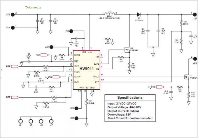
The classic bipolar H-bridge motor driver circuit is a widely used configuration that allows for the control of DC motors in both forward and reverse directions. This circuit utilizes four transistors arranged in a bridge configuration, which enables the reversal of current flow through the motor. The schematic representation of this circuit typically includes the four transistors, which can be either bipolar junction transistors (BJTs) or MOSFETs, depending on the desired characteristics and performance requirements.
In the breadboard photo, the physical layout of the circuit can be observed, showcasing the arrangement of components, including the transistors, resistors, diodes, and the motor. The breadboard setup is essential for prototyping and testing the circuit before finalizing the design on a printed circuit board (PCB).
The parts list includes all necessary components for constructing the H-bridge motor driver circuit. This typically encompasses the transistors, resistors for base or gate control, flyback diodes to protect against voltage spikes generated by the motor, and any additional components necessary for proper operation, such as capacitors for filtering.
The results of several transistor variations indicate the performance differences when using different types of transistors. For instance, BJTs may provide different switching characteristics compared to MOSFETs, affecting efficiency, heat dissipation, and response time. Testing various configurations allows for optimization of the circuit for specific applications, ensuring reliable operation under varying load conditions.
Overall, the combination of the schematic, breadboard photo, parts list, and experimental results provides a comprehensive overview of the classic bipolar H-bridge motor driver circuit, facilitating understanding and implementation in various electronic projects.Schematic, breadboard photo, parts list, and results of several transistor variations on the classic bipolar hbridge motor driver circuit.. 🔗 External reference
Related Circuits
This simple circuit can provide hours of enjoyment as you learn tunes, play duets or just make some really weird sounds by pushing all the buttons at once. You have probably seen this circuit before, it is fairly common....
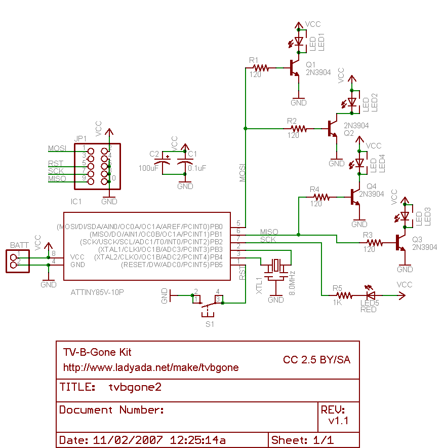
Why use one resistor and one transistor for each LED instead of connecting the LEDs in series and controlling them with a single transistor? This approach is controlled by an Arduino pin through a single resistor. While there is...
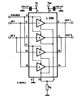
The L298 IC H-Bridge DC motor driver features two H-Bridge circuits, allowing it to control two DC motors simultaneously. Each H-Bridge can deliver currents up to 2A, but when used in parallel, the L298 can provide a total current...
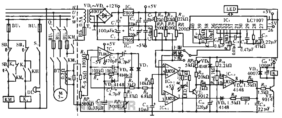
The circuit operates during standard inspection work by utilizing the voltage across resistor R2, which is connected to RP, to generate the input signal for IC4. Components R3 through Rg, along with capacitors C7 and C1, and diodes VD7...
Conventionally, a MOSFET with a voltage rating of 1500V or a Half-Bridge configuration utilizing two MOSFETs rated at 800-900V is employed for Switch Mode Power Supply (SMPS) applications that require input voltages exceeding 380Vac. However, these methods present challenges,...
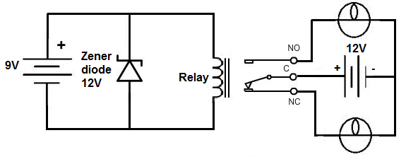
This project involves the construction of a relay driver suitable for both DC and AC relays. Since DC and AC voltages operate differently, the setups for their respective relay drivers require slight variations. A generic relay driver that can...