
High Brightness Boost Led Driver With 1:3000 Dimming Ratio And Excellent Current Regulation

The performance of the high input voltage flyback converter is illustrated in Figure 1, which depicts the design of a 25-watt flyback converter with an output of (+5V, 5A), operating at a switching frequency of 50kHz and high input voltages ranging from 380 to 500Vac. This type of switching power supply is suitable for applications that necessitate high input voltages, such as inverters and other instruments. The discontinuous mode flyback converter employs a KA3844 current mode controller, which ensures effective voltage tracking through pulse-by-pulse current sensing on the primary side, alongside an isolated secondary feedback loop. The KA3844 PWM integrated circuit directly drives the power IGBT.
The 25W flyback converter design leverages the SGL5N150UF IGBT, chosen for its ability to handle high voltage and current levels efficiently. The flyback topology is particularly advantageous for applications requiring electrical isolation and voltage transformation. The KA3844 controller facilitates the regulation of output voltage by adjusting the duty cycle of the switching signal, which is critical for maintaining stable operation under varying load conditions.
In this configuration, the input voltage, which can range from 380Vac to 500Vac, is first rectified and filtered to provide a stable DC voltage for the IGBT. The IGBT acts as a switch, controlling the energy transfer from the input to the output via the transformer. The transformer not only steps down the voltage but also provides the necessary isolation between the high voltage input and the low voltage output.
The feedback mechanism, which utilizes isolated secondary feedback, allows for accurate monitoring of the output voltage, ensuring that any deviations are promptly corrected. This is achieved through the pulse-by-pulse current sensing feature of the KA3844, which enhances the reliability and performance of the converter by preventing overcurrent conditions.
Overall, this flyback converter design represents a significant advancement in the field of power electronics, particularly for applications requiring robust performance under high input voltages, while also addressing the challenges associated with traditional MOSFET-based solutions.Conventionally a MOSFET with a voltage rating of 1500V or with a Half-Bridge connection using two MOSFETs of 800-900V, would be used for SMPS applications requiring input voltages higher than 380Vac. However, these methods have the disadvantages of a complicated circuit structure and high cost. FSC developed a more effective solution: a power IGBT rated at 1500V-5A. This technical note, describes the design of the 25W flyback power supply using a SGL5N150UF. The major experimental operational characteristics of the IGBT are also explained. Performance in High Input Voltage Flyback Converter Figure 1 shows the design of a 25 watt flyback converter with an output at (+5V, 5A), operating at a switching frequency of 50kHz and high input voltages of 380 - 500Vac. This type of switching power supply is used for applications requiring high input voltages such as an inverter and other instruments.
This discontinuous mode flyback converter using a KA3844 current mode controller features good voltage tracking by using the pulse by pulse current sensing on the primary side, and an isolated secondary feedback loop. The KA3844 PWM IC directly drives the power IGBT 🔗 External reference
Related Circuits
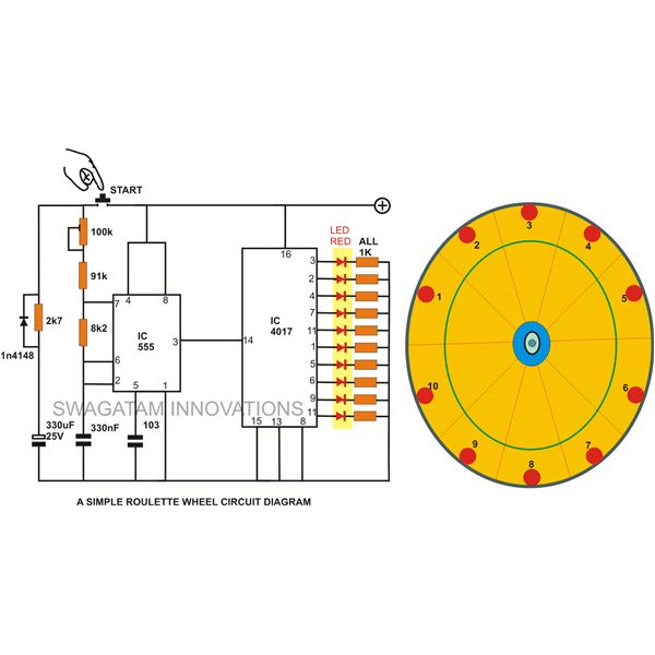
A simple circuit for a 10 LED roulette wheel is presented. Pressing the button initiates the LEDs in a rotational sequence that starts at full speed and gradually decelerates until it halts at a randomly selected LED. The randomness...
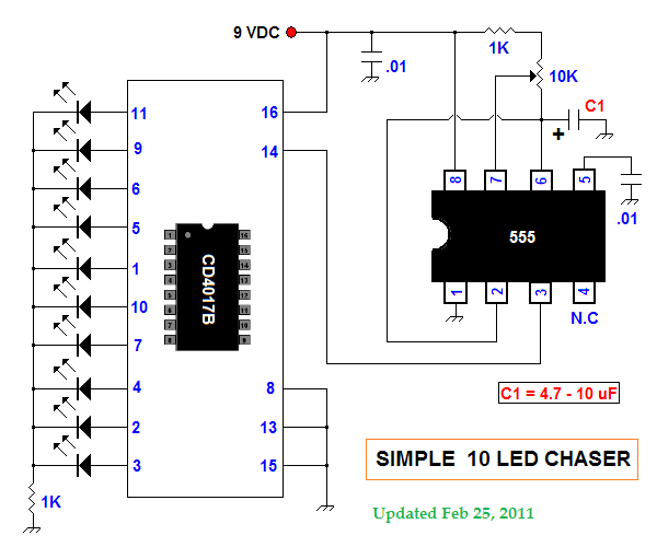
This summer, several LED projects were constructed, including sequential LED chasers that operate from left to right and a Nite-Rider style that moves sequentially left, right, left, right, and so on. These projects are enjoyable for children to experiment...

A mobile-controlled robot is a mobile device that offers extensive wireless control capabilities to the robot, as long as the cell phone remains within signal range. The mobile-controlled robot operates through a wireless communication interface, typically utilizing Bluetooth or Wi-Fi...

Many integrated circuits possess undocumented features or capabilities. One such example is the TLC555, which can sink a 100mA load down to 1.28V at its output (pin 3). The open-drain transistor reset (pin 7) can also sink 100mA to...

This project involves an electronic lock that supports numerous combinations, which can be easily modified. It unlocks only with the correct sequence of four consecutive numbers. A significant feature of this electronic lock is that the four numbers must...
An exhaust fan is a crucial component in kitchens. This document presents a simple circuit designed to control kitchen fans by monitoring the ambient temperature. It is built around... The circuit for controlling an exhaust fan based on ambient temperature...