
Bird Feeder Monitor Circuit

This bird phone circuit utilizes an electret microphone (MIC1) positioned within a funnel to effectively capture sounds from a bird feeder. The funnel design serves to enhance the microphone's sensitivity to distant sounds, focusing the audio capture capability. The MC34119 operational amplifier is central to the circuit, providing the necessary amplification for the microphone's low output signal.
The configuration of the amplifier includes an input resistor (R1) and two feedback resistors (R3 and R4) that establish the circuit's gain. The gain formula, (R2 + R1) / R1 x 2, indicates that the gain is influenced by the ratio of the feedback and input resistors, allowing for precise control over the amplification level. With a maximum voltage gain of approximately 270, the circuit is capable of amplifying the sounds of birds feeding, making it an effective tool for birdwatching enthusiasts.
The output of the amplifier is connected to a 16-ohm speaker, enabling real-time audio playback of the amplified sounds. This setup not only enhances the listening experience but also allows for a deeper appreciation of the subtle sounds of nature. Proper placement of the microphone and amplifier is crucial to maximize sound capture while minimizing background noise, ensuring that the bird phone functions optimally in its intended environment. The first amplifier circuit is a bird phone. In this circuit, the electret mike (MIC1) is mounted in the neck of a large plastic funnel. The amplifier, built around an MC34119 (which is available from D.C. Electronics, P.O. Box 3203, Scottsdale, AZ 85271-3203; Tel. 800-467-7736, and elsewhere), is then placed outside of the funnel with the pickup facing a nearby bird feeder. The output of the amplifier is then connected to a 16- speaker. The amplifier`s voltage gain is determined by the values of the input resistor (Rl) and the feed-back resistor (R3 and R4, respectively).
The differential gain of the amplifier is given by: R2 + RJR} x 2. With the component values shown, the maximum voltage gain is about 270. This permits listening to the activity at the bird feeder.
Related Circuits
This circuit is constructed using two LT1001 operational amplifiers (OP-AMPs), with the output of the OP-AMP saturating at +5V. The power supplies used are +5V and ground. According to the documentation, applying +1V to the "Servo Input" results in...
This circuit can be used for detecting infrared light; for example, it is utilized for detecting infrared band light signals in a spectrophotometer. The amplifier output voltage Vo is given by the formula Vo = Is·Rd·Rf/Ri, where Is is...
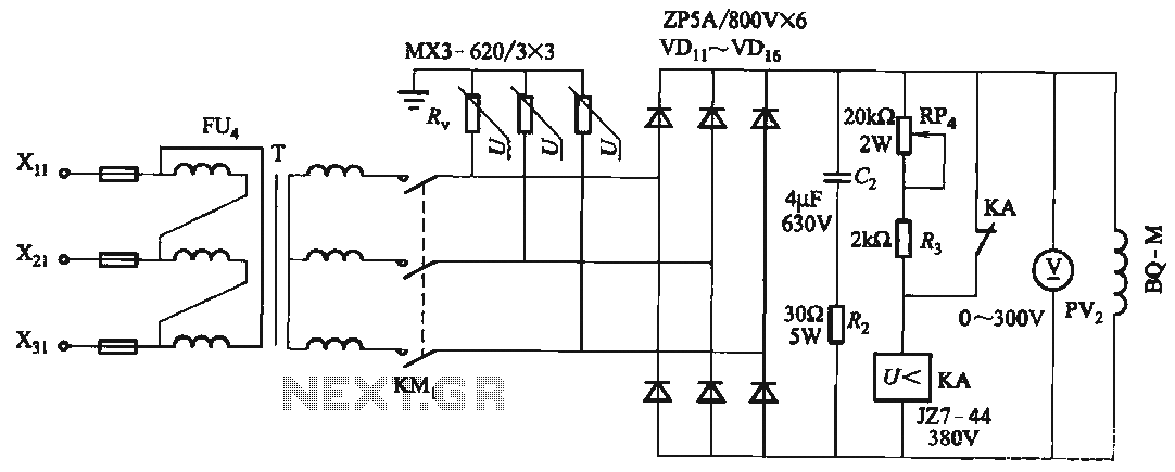
FIG T is the excitation transformer, R is a varistor, and there are rectifier diodes to protect against breakdowns from VDii to VD16; Rz and C2 provide resistive-capacitive protection. The circuit is designed to absorb voltage from the magnetic...

TDA7262 stereo 20 watts audio amplifier circuit design electronic project The TDA7262 is an integrated circuit designed for stereo audio amplification, capable of delivering up to 20 watts per channel. This amplifier circuit is suitable for various applications, including home...
The transmitter described here includes an additional RF power amplifier stage following the oscillator stage, which increases the output power to 200-250 milliwatts. When connected to a properly matched 50-ohm ground plane antenna or a multi-element Yagi antenna, this...
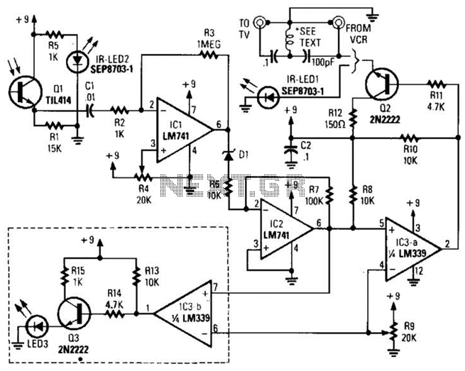
A signal from an infrared (IR) remote control is converted from IR radiation to a frequency pulse that can be transmitted through coaxial TV cable or any other two-conductor wire to another room, where it is converted back into...