
Metering circuit using PbS PbSe

The described infrared light detection circuit is essential for applications such as spectrophotometry, where precise measurement of light intensity in the infrared spectrum is critical. The circuit typically comprises an optical detector, which can be either a lead sulfide (PbS) or lead selenide (PbSe) photoconductor. These materials are chosen for their sensitivity to infrared wavelengths, making them suitable for various applications in optical sensing.
The operational principle of the circuit relies on the generation of a signal current (Is) when infrared light strikes the detector. The current produced is directly proportional to the intensity of the incoming infrared light. The essential resistance (Rd) of the optical detector plays a significant role in determining the overall sensitivity and performance of the circuit. The output voltage (Vo) from the amplifier is calculated using the formula Vo = Is·Rd·Rf/Ri, where Rf is the feedback resistance and Ri is the input resistance.
In the circuit design, careful selection of the feedback and input resistances is crucial to optimize the gain and bandwidth of the amplifier, thereby ensuring accurate signal amplification. The circuit may also include additional components such as capacitors for filtering and stability, as well as protection diodes to prevent damage from over-voltage conditions.
Overall, this infrared light detection circuit represents a fundamental building block for devices that require the measurement of light in the infrared spectrum, with applications ranging from environmental monitoring to industrial process control.This circuit canbeused for detecting infrared light, for example, it is used for detecting infrared band light signal in spectrophotometer. Amplifier output voltage Vo=Is·Rd·Rf/Ri wherein : Is-signal current; Rd-optical detector essential resistance Dector can bemade by lead sulphide (PbS) or lead selenide (PbSe), and at room temperature, PbS response..
🔗 External reference
Related Circuits

This is a circuit diagram for a simple doorbell. The circuit can be assembled indoors, while the switch should be placed outside, making it easily noticeable for visitors. The operation of this circuit is similar to a previous project. The...

This method reduces starting current and starting torque. The device typically consists of three contactors, an overload relay, and a timer for setting the duration in the star position (starting position). The motor must be delta connected during normal...
This precise one-pulse-per-second clock is constructed using a few common components and is powered by a 50 or 60 Hertz mains supply without any direct connection to it. A beep or metronome-like click, along with a visible flash, indicates...
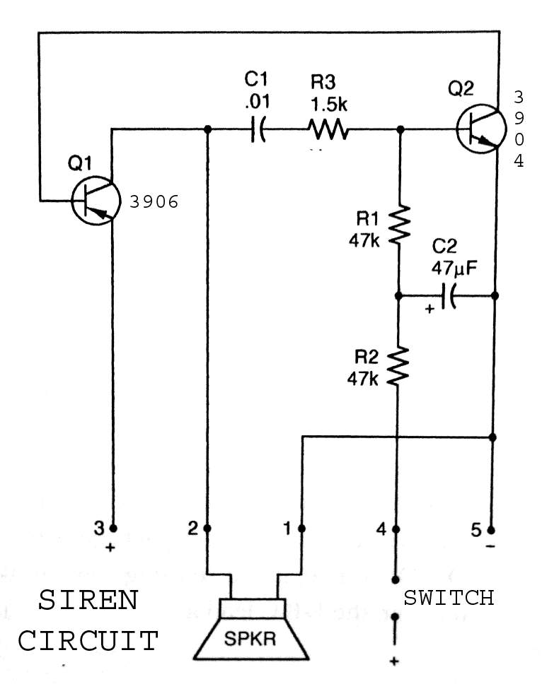
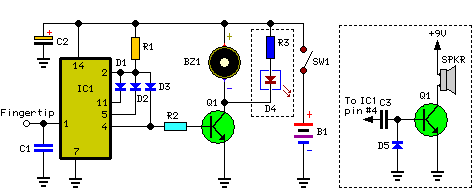
3904 3906 Siren Circuit. The circuit generates a wailing siren sound when the switch is activated. The 3904 3906 Siren Circuit is designed to produce a distinctive wailing sound, commonly used in alarm systems and signaling devices. The circuit utilizes...

Upon purchasing the slave dial, it arrived without instructions, packaging, or additional details. The only visible markings, aside from decades of grime, were on the face (SMITH SECTRIC, ACELEC SYDNEY) and some markings on the bracket holding the mechanism...

The diagram features a micro memory capable of storing up to 64 different addresses, each containing 15 bits, referred to as micro operations (MOPs). These MOPs govern all functions of the computer. Adjacent to the micro memory is the...