
Blackout emergency lights circuit 2

The emergency lamp circuit is designed for reliable operation during power outages, ensuring that illumination is maintained when the main power supply fails. The transformer (T) steps down the line voltage to a suitable level for the circuit components. The rectification process is accomplished using diodes VD1 through VD4, which convert the alternating current (AC) from the transformer into direct current (DC). The capacitor (C) smooths the rectified output, providing a stable voltage to charge the battery (G).
When the main power is available, the circuit operates in a standby mode. The current flows through the circuit, charging the battery while keeping transistor VT1 in the off state. This configuration ensures that the small lamp does not illuminate during normal operation, conserving battery power for use during an outage.
Upon loss of mains power, diode VD5 prevents the battery from discharging back into the grid. The absence of voltage at the base of VT1 causes it to turn off, which in turn allows VT2 to become active. The base of VT2 receives bias from the charged battery, enabling it to conduct and power the emergency lamp. This design allows for a seamless transition from grid power to battery power, ensuring that the emergency light is activated promptly during a power failure.
The circuit's components are selected to meet standard operational requirements, and no specific parameters are needed beyond those depicted in Figure 282. This circuit is suitable for various applications, providing an essential safety feature in residential and commercial settings.Figure 282 foot another simple power outage should emergency lamp circuit. When the grid is often only power and municipal electricity by T Buck, VD1 ~ VD4 rectification, C- cr ossing and filtered through R. And VD5 to the battery (; charged at this time,. VT1 closing R. positively skewed by conduction, its collector is low, so V, r2 is turned off, a small lamp is not lit when the mains F. LU sudden power outage, due to the isolation VD5, G will not supply power to the pole by R. VT1 base, VT] and idle power cut off, thereby lifting the VT2 blockade, VT2 base due by foot from the battery G obtained bias conduction, Eagle will be powered emergency lights E hair light, thin pressure device T, the battery (G small and light E to seek common ground seven cases, the other component parameters Figure, no special requirements.
Related Circuits
Although labelled as distortion, this is a soft clipping device, using germanium diodes. It's a good example of how little you need for a good basic sound. You could easily swap (or switch) these diodes to silicon types for...
This tremolo effect circuit utilizes the XR2206 and the TCA730 integrated circuits, which are designed as an electronic balance and volume regulator with frequency correction. The tremolo effect circuit operates by modulating the amplitude of an audio signal, creating a...
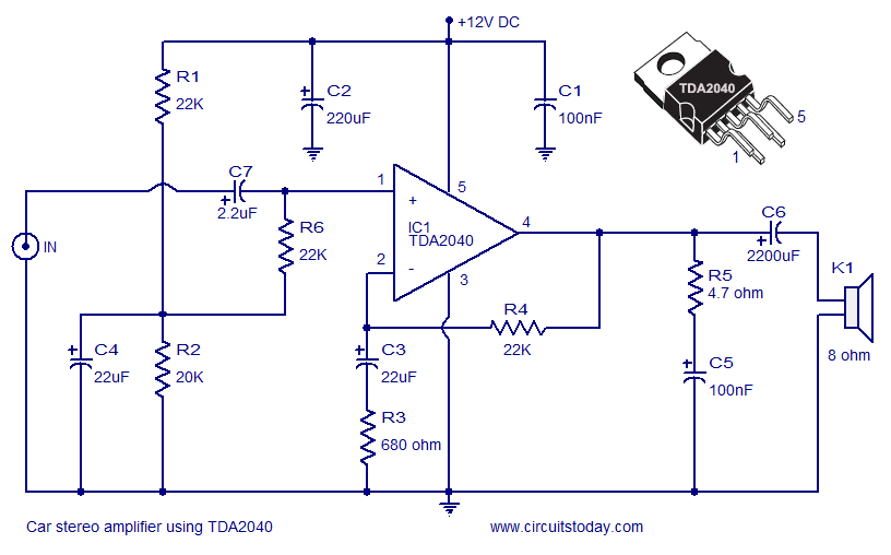
A car stereo amplifier circuit utilizing the TDA2040 is presented here. The TDA2040 is a monolithic integrated audio amplifier that functions in Class AB mode. This integrated circuit features built-in short circuit protection and thermal shutdown capabilities, and it...
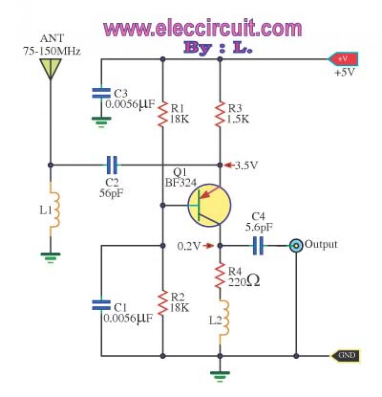
This is a wideband high-frequency amplifier circuit designed for a frequency range between 75-150 MHz. It utilizes a PNP transistor amplifier to enhance signal strength before it reaches the receiver of devices such as phones, FM radios, or amateur...
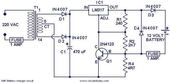
This is a simple charger circuit designed for charging sealed maintenance-free (SMF) batteries. The circuit is both current and voltage regulated, making it safe for charging SMF batteries with a rating of 1.2 AH. It can be modified slightly...
This radio receiver can operate with any of the following transistors: ZN414, MK484, or TA7642. The radio receiver circuit is designed to utilize a variety of transistors, specifically the ZN414, MK484, and TA7642, which are commonly used in low-power AM...