
Car Amplifier Circuit Schematic using TDA2040 Integrated Audio Amplifier

The TDA2040 amplifier circuit is designed for automotive audio applications, taking advantage of its Class AB operation to provide efficient amplification with low distortion. The use of a single supply voltage simplifies the design, making it suitable for integration into vehicle audio systems. The circuit's configuration allows it to effectively manage power delivery while maintaining sound quality.
The input stage includes capacitor C7, which blocks any DC offset from the audio source, ensuring that only the AC audio signal is amplified. The feedback provided by resistor R4 is critical for maintaining the desired gain and stability of the amplifier. The high-frequency stability network, consisting of resistor R5 and capacitor C5, is essential for preventing unwanted oscillations that could compromise audio performance or damage the amplifier.
Capacitor C6 plays a vital role in coupling the output of the TDA2040 to the speaker. This capacitor allows the amplified audio signal to pass while blocking any DC component, which could potentially damage the speaker. The power supply filtering capacitors, C1 and C2, are crucial for maintaining a stable voltage supply to the amplifier, reducing noise and ripple that could affect the audio output.
Overall, this circuit exemplifies a robust design for automotive audio amplification, leveraging the features of the TDA2040 to deliver reliable performance in a compact form factor.A car stereo amplifier circuit using TDA2040 is shown here. TDA2040 is a monolithic integrated audio amplifier that operates in Class AB mode. The IC has built in circuitry for short circuit protection and thermal shut down and more over it can be operated from a single supply too. The amplifier can deliver 12 watts into to a 8 ohm speaker. In the circuit the IC is wired in order to operate from the cars 12V line. Capacitor C7 is the input DC decoupling capacitor and R4 provides feedback. Network consisting of resistor R5 and capacitor C5 provides high frequency stability and prevents any chance of oscillation. Capacitor C6 couples the ICs output to the speaker. C2 and C1 are power supply filters. 🔗 External reference
Related Circuits
Pulse position modulation is similar to pulse width modulation, but the frequency is not constant. Like pulse width modulator circuit, pulse position modulation... Pulse Position Modulation (PPM) is a modulation technique in which the position of a pulse within a...
Capacitors C1 and C2, in conjunction with a speed controller, function by receiving voltage at the gate of the MOSFET. When the voltage on C is applied, it activates the operation of the MOSFET. In this circuit configuration, capacitors C1...
Although many album titles once available on vinyl are gradually being released as CDs, not all are accessible, leaving some valuable treasures in collections that individuals may wish to transfer to CDs. Preserving a CD is generally easier than...
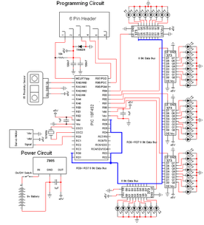
The personal radar system utilizes the PIC microcontroller PIC18F452 as a hobby project. The attached circuit diagram of the radar may appear simple; however, careful analysis of the PIC18F452 radar circuit is necessary to prevent damage. This personal radar...
A peak level indicator is a device that signals when a signal surpasses a specific maximum value. It proves to be particularly beneficial in applications such as tape recorders and mixing consoles. A crucial requirement for a peak level...
This schematic illustrates a beeper circuit designed to produce a continuous beep sound while simultaneously flashing an LED. The beeper circuit typically consists of a few key components: a sound-generating device (such as a piezo buzzer), an LED for visual...