Blanket internal measurement circuit disconnection
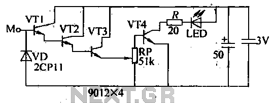
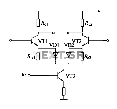
The internal disconnection circuit for a blanket operates on the principle of induction. It includes a wire approximately 2 cm in length that senses the proximity of a charged mains power source. When the sensing wire is close to the power source, an induced voltage is generated, which is rectified by transistors VT1 to VT3, forming a composite amplification circuit. Transistor VT4 is added to the base circuit to ensure its conduction. The LED indicator displays the operational status: when the sensing element is away from the live wire or when the live wire is not energized, no induced voltage is present at VT1-VT3, resulting in no output. Consequently, VT4 receives insufficient bias and turns off, causing the LED to extinguish. Component selection includes transistors with a gain of 20 and a minimal IEEO; light-emitting diodes can be chosen from various models; and the resistor R typically has a value in the range of several tens of ohms, while RP is a variable resistor. During testing, an inductor (induction test pencil) should be brought close to the live wire, and the resistance of RP should be adjusted until the LED turns off and on accordingly. When testing electric blankets, the heating wire and two connections must be disconnected from the power line, with one end insulated and the power cord connected to the live wire. This setup prevents electric shock while allowing for testing of the induction heating wire. If the LED turns off during the proximity test, a break in the circuit has been identified.
The blanket internal disconnection circuit is designed to enhance user safety by detecting when the blanket is not in close proximity to a person. This circuit utilizes the principle of electromagnetic induction to monitor the presence of a user. The sensing wire, positioned within the blanket, acts as an inductive sensor. When a user is nearby, the induced voltage from the mains power is sufficient to activate the transistors in the circuit, allowing current to flow through the LED indicator, signaling that the blanket is operational.
The use of transistors VT1 to VT3 for rectification and amplification is critical for ensuring that even small induced voltages can be effectively processed. The configuration allows for the detection of minute changes in voltage, which may occur when the user moves away from the blanket. The additional transistor VT4 serves as a control element that responds to the output from the first three transistors. When the system is operational, VT4 is biased into conduction, allowing the LED to illuminate.
Component selection is pivotal for the circuit's reliability. Transistors with a gain of 20 are recommended to ensure sufficient amplification of the induced signal. The choice of light-emitting diodes should be based on their visibility and power rating, ensuring they can handle the expected current without failure. Resistors, particularly RP, should be adjustable to allow for fine-tuning of the circuit during the testing phase, permitting the user to establish the threshold at which the LED toggles based on the proximity of the user.
During debugging and testing, the use of an induction test pencil is essential. This tool allows for safe verification of the circuit’s functionality without exposing the tester to high voltages. By adjusting the variable resistor RP while monitoring the LED, one can confirm the operational status of the disconnection circuit. If the LED extinguishes when the test pencil is moved away from the live wire, it indicates that the circuit is functioning correctly and that the sensing wire is effective in detecting the absence of a user.
In practical applications, the safety measures implemented in this circuit, such as disconnecting the heating wire and insulating connections, are crucial for preventing electrical hazards. This design not only prioritizes user safety but also ensures that the blanket remains functional and efficient, providing warmth only when needed. The meticulous selection of components and attention to circuit design principles contribute to a reliable and safe user experience.Look for the blanket internal disconnection circuit, its working principle is: M spot welding have a wire about 2cm induction body, when a sense of when to be close to the body charged mains FireWire side by VD induced voltage is rectified by the VT1 ~ VT3 a composite tube amplification, VT4 was added to the base, so that VT4 conduction. LED light-emitting display: When the susceptor away from the line of fire or fire when the line is not live, because no induced voltages VT1-VT3 no output, VT4 was less bias and off, LED off.
Component selection and production as follows. Transistor value g 20, Ieeo as small as possible; light-emitting diodes I. ED can choose one model; the value of the resistor R is generally several tens Europe, RP semi-variable resistor. When debugging, you should inductor (induction test pencil) live near the line of fire, change the resistance of RP, the LED goes out to the light.
When away from the line of fire when, I. ED should be extinguished. When using test pencil checking electric blankets, heating wire and two joints should be power line disconnect any one package with an insulating cloth broken thread wrapped on one side and then the power cord is connected and plugged into a live wire resistance FireWire catch hole (to prevent electric shock, but also enough to withstand a series of small electric capacity), so close to the body test pencil induction heating wire is not disconnected from the far end of sequentially looking for, once the LED goes out, they found at the break.
