
Tracking Transmitter Circuit

The tracking transmitter is a sophisticated device designed for precise signal transmission and tracking applications. It integrates four essential components that work together seamlessly.
The free-running multivibrator serves as the timing circuit, generating a continuous square wave signal characterized by a pulse width and a pulse separation of 1500 milliseconds. This is crucial for maintaining a stable output frequency, which is determined by the values of the resistors and capacitors used in the circuit. Transistors Q1 and Q2 are configured in a feedback loop to ensure oscillation, with their collector and emitter configurations carefully selected to achieve the desired pulse characteristics.
The output from the multivibrator is coupled to the base of transistor Q3 through resistor R5. This coupling serves to amplify the pulse signal generated by the multivibrator. Q3 functions as an intermediate amplifier, providing sufficient drive to transistor Q4. The emitter of Q3 is connected to the base of Q4, which acts as a switch to control the transmitter section of the circuit.
The transmit switch, which is part of the overall architecture, allows for the modulation of the signal for transmission. This section is responsible for turning the transmitter on and off as needed, ensuring efficient power usage and signal integrity.
The audio-tone generator produces a modulating tone that can be superimposed on the transmitted signal, enhancing the tracking capabilities of the transmitter. This audio tone can be adjusted based on the requirements of the tracking application.
Finally, the FM transmitter section is responsible for broadcasting the modulated signal over a specified frequency range. This section typically includes additional components such as an antenna and frequency-determining elements to ensure compliance with regulatory standards for transmission.
Overall, the design of this tracking transmitter emphasizes reliability and precision, making it suitable for various applications in tracking and monitoring systems. This tracking transmitter consists of four distinct subassemblies; a free-running multivibrator, a transmit switch, an audio-tone generator, and an FM transmitter. The multivibrator (which produces a pulse width with a pulse separation of 1500 ms) is built around Ql and Q2.
The multivibrator output is coupled through R5 to the base of Q3, whose emitter feeds Q4, which controls the circuit`s transmitter section.
Related Circuits
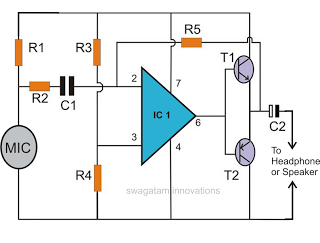
This circuit features a microphone and preamplifier that take precedence over any other audio signal, functioning similarly to a one-way intercom. When the push-to-talk switch is activated, the main amplifier switches from music playback to the voice signal. Essentially,...
This schematic illustrates a simple yet effective LED dimmer circuit utilizing the well-known voltage regulator IC LM317T. The LM317T can function as a current regulator, as demonstrated in this circuit. It features ten super bright white LEDs, although the...
This document discusses the creation of an electronic spy bug circuit using two methods: one involving a wired connection from the transmitter to the receiver, and the other being a completely wireless setup capable of eavesdropping on conversations up...
The figure below illustrates the use of a relay in the starting circuit. The power input connects through a resistor R, which serves two purposes: first, it prevents a large current from the capacitor C1 from affecting the power...
The power output of most of these circuits is very low because no power amplifier stages were incorporated. The transmitter circuit described here has an extra RF power amplifier stage, after the oscillator stage, to raise the power output...
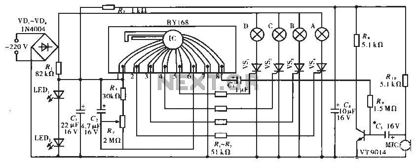
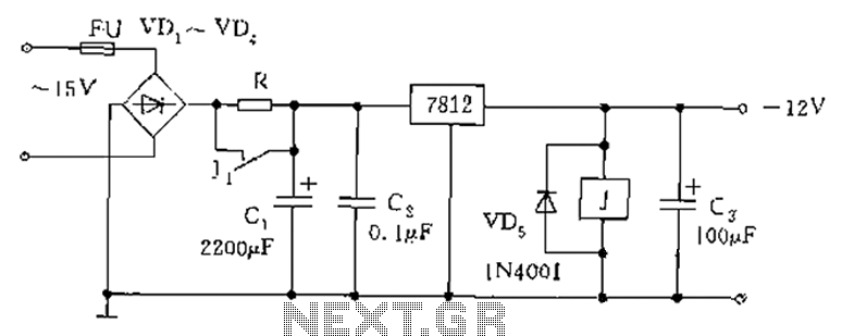
The circuit operates with a controller that includes a power supply circuit, a control circuit, and an audio amplifier, which are three distinct components. The power circuit comprises diodes VD1 to VD4, resistor R1, capacitor C1, LED1, LED2, and...