
Blinker Indicator

The described circuit utilizes a NAND gate (IC1) to manage the reset pulse for a counter mechanism, which is responsible for sequentially illuminating a series of LEDs. The counter increments its count each time the lamp is turned off, triggering a reset that allows the counting process to restart. The adjustment of the display's progression rate is achieved through the use of potentiometer P1, providing flexibility in how quickly the LEDs cycle through their illumination sequence.
The design ensures that only one LED is lit at a time, which serves to enhance visibility and manage power consumption effectively. The exception to this rule is the hazard blinker, which may illuminate multiple LEDs simultaneously for alert purposes. The brightness of the LEDs can be fine-tuned with resistor R12, allowing for user customization based on ambient lighting conditions or personal preference.
Furthermore, the circuit offers versatility in its component selection. By replacing standard diodes with LEDs, the circuit can be adapted to utilize LED technology, which may provide additional benefits such as lower power consumption and longer lifespan. In this modified configuration, the cathodes of the LEDs are connected to ground through resistor R12, maintaining the circuit's operational integrity while enhancing the visual output.
Overall, this circuit design presents a straightforward yet effective approach to managing LED displays, with adjustable parameters that cater to a range of user needs and preferences.When the lamp goes out, a new reset pulse is issued to the relevant counter by NAND gate IC1. A or IC1. B respectively, and the counter counts all the way up again. The progression rate of the display can be adjusted to the right speed using P1. Only one LED is on at a time (except for the hazard blinker). This allows the brightness to be easily adj usted using R12. Incidentally, the circuit can also be modified by replacing the normal diodes with LEDs, with all of the cathodes connected to ground via R12. Be the first of your friends to get free diy electronics projects, circuits diagrams, hacks, mods, gadgets & gizmo automatically each time we publish.
Your email address & privacy are safe with us ! 🔗 External reference
Related Circuits
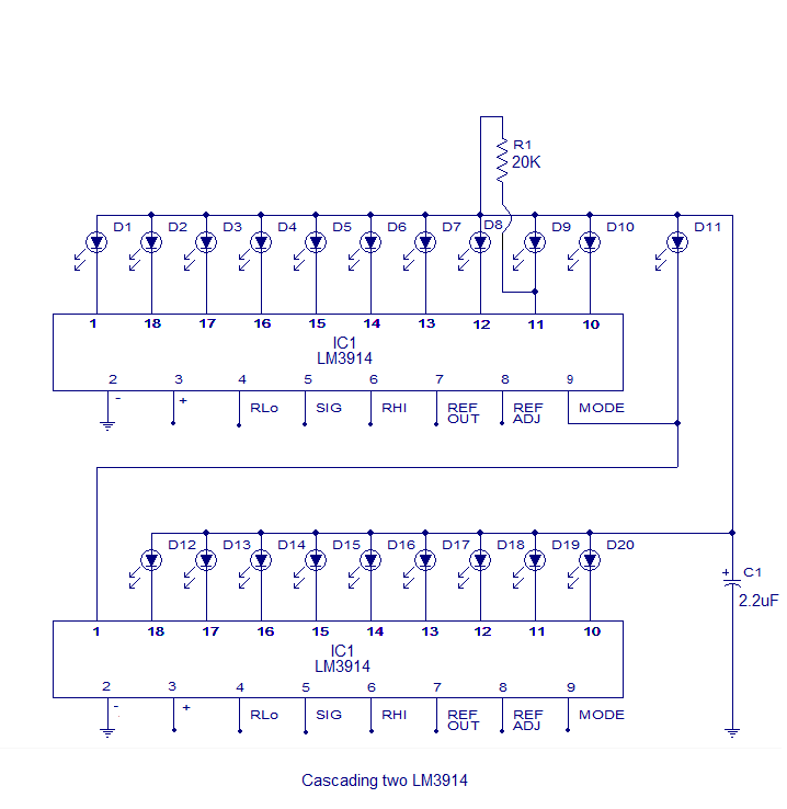
The core of this circuit is the LM3914 from National Semiconductor. The LM3914 is capable of sensing voltage levels and can drive a display of 10 LEDs in either dot mode or bar mode. The selection between bar mode...
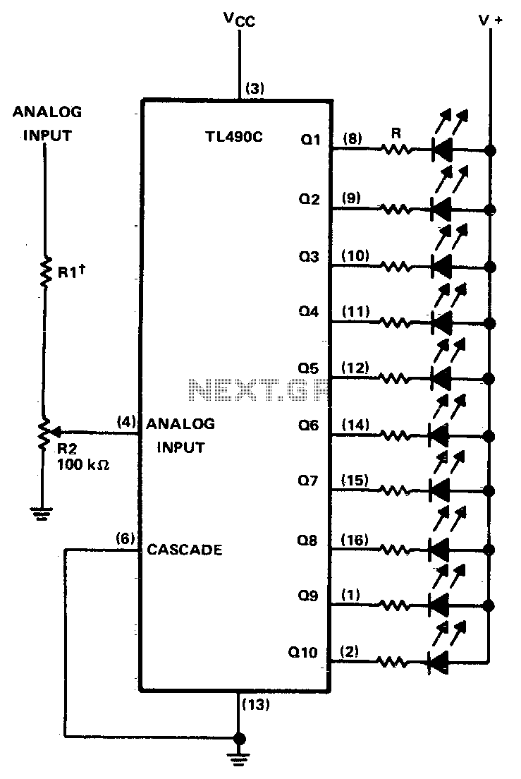
This ten-step adjustable analog level detector is capable of sinking up to 40 milliamperes at each output. The voltage range at the input pin should range from 0 to 2 volts. Circuits of this type are useful as liquid-level...
This is a battery tester circuit. This circuit is used to indicate whether the level of a battery voltage is normal, under-voltage, or over-voltage. The battery tester circuit is designed to assess the voltage level of a battery and provide...

This circuit is intended to indicate the power output level of any audio amplifier. It is simple, portable, and displays three power levels that can be set to any desired value. IC1A is the input buffer, feeding 3 voltage...

Continuous monitoring of mains voltage is essential in various applications, including manual voltage stabilizers and motor pumps. Although an analog voltmeter is cost-effective, it has several drawbacks due to its moving parts and sensitivity to vibrations. The solid-state voltmeter...

The LED indicator in this project can be used for bike indicators or car direction indicators. A 555 timer and a BCD 7490 are utilized along with several resistors, exceeding 100 in total across various electronic projects. The circuit employs...