
LED Audio Power Indicator

This audio power level indicator circuit is designed to provide a visual representation of the output power levels from an audio amplifier. The circuit utilizes a standard operational amplifier (IC1A) configured as an input buffer to ensure that the input impedance is high enough to avoid loading the amplifier output. The buffered signal is then fed into three voltage comparators, which compare the buffered audio signal to predetermined reference voltage levels set by a voltage divider network.
The output of each comparator is connected to an LED driver, which illuminates corresponding LEDs to indicate the power output level. The reference voltages can be adjusted to accommodate different amplifier outputs, allowing for flexibility in monitoring various audio devices. The smoothing action provided by resistor R5 and capacitor C4 ensures that the signal is stable and free from noise, enhancing the accuracy of the readings.
For optimal setup and calibration, an oscilloscope or an audio millivoltmeter is recommended to measure the output of the amplifier accurately. This allows for precise adjustment of the reference levels to ensure that the LED indicators accurately reflect the power levels being output by the amplifier. Additionally, a 1KHz sine wave generator with variable output is necessary for testing purposes, enabling the user to simulate various audio signals and observe the corresponding LED responses.
The circuit can be easily connected to the amplifier's output using a twisted pair cable, which helps to minimize interference and maintain signal integrity. The use of insulated crocodile clips for connection ensures safety and ease of use during setup. Overall, this circuit is a practical solution for audio engineers and enthusiasts seeking to monitor amplifier performance in real-time.This circuit is intended to indicate the power output level of any audio amplifier. It is simple, portable, and displays three power levels that can be set to any desired value. IC1A is the input buffer, feeding 3 voltage comparators and LEDs drivers by means of a variable dc voltage obtained by R5 and C4 smoothing action. The simplest way to connect this circuit to the amplifier output is to use a twisted pair cable terminated with two insulated crocodile clips.
Setup is best accomplished with an oscilloscope or an audio millivoltmeter like the one described in these pages. Precision Audio Millivoltmeter A 1KHz sine wave generator with variable output is also required (see a suitable circuit in this website als
🔗 External reference
Related Circuits
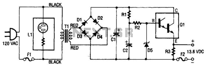
This regulated power supply consists of a step-down transformer T1, a full-wave rectifier bridge (D1 through D4), and a filtering regulator circuit made up of C1, C2, R1, R2, R8, D5, and Q1. When 120 Vac is provided, the...
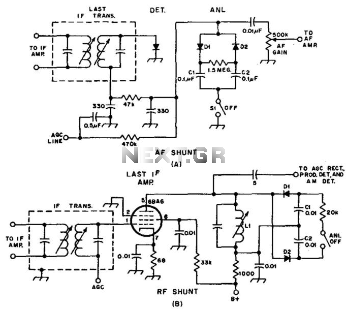
Examples of RF and audio ANL circuits. Positive and negative clipping occurs in both circuits. The circuit is self-adjusting. This noise limiter operates at the IF output. Adequate gain is needed at the IF frequency so that several volts...
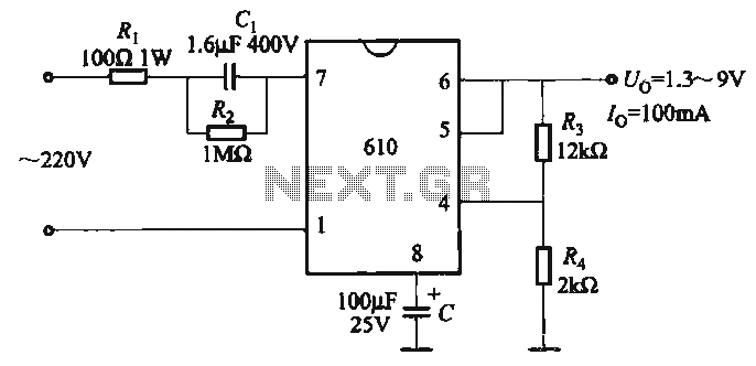
The output voltage can be calculated as follows: U = 1.3 (1 + R3 / R4) (V), where R3 and R4 are part of an adjustment potentiometer, allowing for a continuously adjustable output voltage. The described circuit involves a voltage...
This device is a sensitive instrument that detects frequency changes and the width of an acoustic signal. The brightness of the LED that activates at each moment is proportional to the signal width, while the color corresponds to the...
If a tool is needed to save electricity, a simple power-saving device circuit diagram is suitable for testing. This tool can save electricity in a home by 10-25%. Its operation involves reducing the cosine component of AC current curves,...
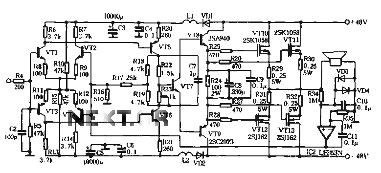
The self-designed amplifier circuit described is completely symmetrical and complementary, effectively utilizing the advantages of complementary NPN and PNP transistors to achieve a high degree of stability. The circuit features good symmetry in the push-pull amplification state, allowing for...