
Bluetooth Based Smart HomeCircuit Based On The ULN2003 IC

The Bluetooth-based smart home circuit utilizes the ULN2003 IC, which is a high-voltage, high-current Darlington transistor array. This IC is instrumental in driving various loads such as LEDs and relays, making it suitable for controlling home appliances through Bluetooth communication. The circuit can be divided into several key components: the Bluetooth module, the ULN2003 IC, the LCD display, and the LED indicators.
The Bluetooth module, typically an HC-05 or HC-06, facilitates wireless communication between a smartphone or computer and the smart home circuit. This allows users to send commands to control various devices remotely. The module is connected to a microcontroller, which interprets the received Bluetooth signals and sends appropriate control signals to the ULN2003.
The ULN2003 is connected to the microcontroller's output pins, and it can control multiple devices simultaneously. Each output pin of the ULN2003 can drive up to 500 mA of current, making it capable of handling various loads such as light bulbs or small motors. The inputs of the ULN2003 are connected to the microcontroller, which sends a high signal to activate the corresponding output pin.
The LCD display serves as a user interface, providing real-time feedback on the status of the connected devices. It can display messages such as "Device On" or "Device Off," allowing users to monitor their home appliances easily. The LCD is interfaced with the microcontroller using a 4-bit or 8-bit configuration, depending on the desired complexity and number of connections.
LED indicators can be incorporated into the circuit to visually represent the status of the devices being controlled. For example, a green LED can indicate that a device is powered on, while a red LED can signal that it is off. The LEDs are connected to the output pins of the ULN2003 and are activated based on the signals from the microcontroller.
In summary, the Bluetooth-based smart home circuit diagram demonstrates a practical application of the ULN2003 IC in controlling home appliances through wireless communication, with the added functionality of an LCD display for user interaction and LED indicators for device status visualization. This circuit provides an efficient and user-friendly solution for modern smart home automation.The following circuit shows about Bluetooth Based Smart Home Circuit Diagram. This circuit based on the ULN2003 IC. Features: LCD & LED .. 🔗 External reference
Related Circuits
The ICL7665S Super CMOS Micropower Over/Under Voltage Detector features two low-power, individually programmable voltage detectors integrated on a single CMOS chip. It typically requires 3 µA for operation and is designed for battery-operated systems and instruments that need high...
The anti-theft system includes two frequency sirens connected to the vehicle's immobilizer system. In the laboratory simulation model, the changes in operating modes, siren activation, and fuel supply cut-off are indicated by the illumination of LEDs and communicated to...
This project involves an automatic room light controller with a bidirectional visitor counter using a microcontroller. It is designed to manage room lighting and accurately count the number of individuals present. When a person enters the room, the counter...
The prototype was successfully assembled on a breadboard and subsequently built on a piece of Radio Shack protoboard for field use. The assembly process took only a couple of hours, and it functioned correctly on the first attempt. This...
The AmpLoadPull project demonstrates the utilization of the AmpLoadPull and LoadPullSetup components in Advanced Design System (ADS). These components are part of the ADS behavioral model suite located within the System - Data Models palette. The schematic "circuit_level_amplifier_1_tone.dsn" represents...
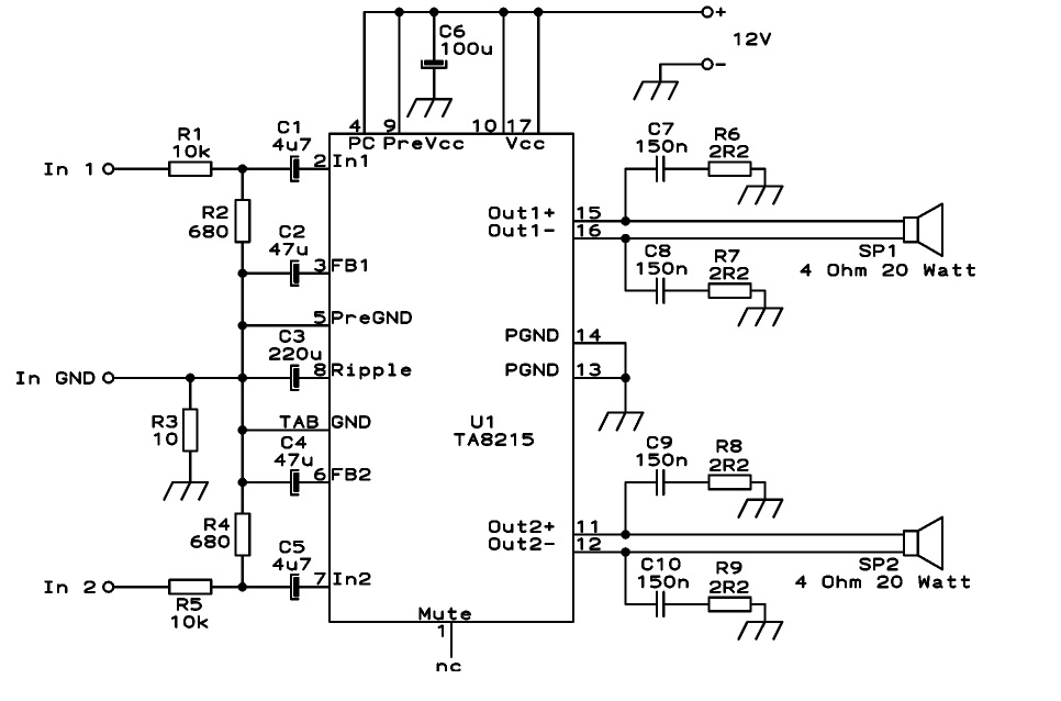
This circuit is designed as a stereo BTL (Bridge-Tied Load) 15W audio power amplifier using the TA8215 integrated circuit developed by Toshiba. Two TA8215 ICs are utilized in this configuration to achieve four output channels, with each IC providing...