
Audio IC TA8215 based on 15W Car Audio Amplifier

The TA8215 amplifier circuit facilitates high-quality audio amplification with a compact design, making it suitable for various audio applications. The choice of a 12 V DC supply voltage allows for compatibility with standard power sources, while the BTL configuration enhances the output power without the need for a transformer. The use of two TA8215 ICs effectively doubles the output channels, making it ideal for stereo applications where space and power efficiency are critical.
The voltage divider formed by resistors R1 and R2 is an essential aspect of the design, as it ensures that the input signal is appropriately attenuated to prevent distortion at higher gain levels. The overall gain of 26 dB strikes a balance between sufficient amplification and maintaining sound quality, allowing the amplifier to operate effectively across different audio sources.
Capacitors C1 and C2 play a crucial role in maintaining signal integrity and preventing unwanted noise during operation. By carefully selecting these components and their arrangement, the circuit minimizes the risk of switch clicks that can occur during power transitions. The output stage, connected directly to the speakers through pins 15 and 16, is designed to handle the maximum output power efficiently, while the additional components (C7, R6, R7, and C8) ensure stability in the presence of high-frequency signals.
The power supply decoupling with a 100 µF capacitor is a practical choice, as it provides adequate filtering for both high and low-frequency noise, improving the overall performance of the amplifier. Furthermore, the configuration of pins 10, 17, and 9 ensures that both the power amplifier and preamp stages receive stable power, which is critical for maintaining consistent audio performance.
Overall, the TA8215-based amplifier circuit is a robust solution for audio amplification, offering a compact design, effective power management, and high-quality sound output, making it suitable for various consumer electronics applications.This is the circuit of the amplifier channel stereo BTL 15W audio power IC based on TA 8215 developed by Toshiba. In this circuit, power amplifier, TA 8215 two ICs are used. This is for the acquisition of four channels has two channels of each IC. TA 8215 is an integrated circuit with the stages of power amplifier and preamplifier integrated insid
e. The power required for this amplifier is only 12 V DC. The maximum output power of each channel of delivery of this amplifier is 15 W at 4 ohm speaker and a so called 4 x 15 W power amplifier. R1 R2 form a voltage divider that attenuates the input signal of 24 dB. Given the 50dB gain of the chip, leaving the total gain of 26dB, a little more than enough to fully saturate the amplifier when the sound card works at maximum output.
DC C1 preamp input blocks. C2 is the ground return of the feedback circuit. These two capacitors have to be in the relationship is shown, in order to remove the switch clicks when turning the circuit on and off. The output pins 15 and 16 are connected directly to the speaker, while C7, R6, R7 and C8 provide adequate loading phase change to avoid high frequency instability.
The power supply is decoupled with a capacitor of 100uF rather small. That`s enough to decouple the higher frequencies and lower frequencies anyway large capacitors in power supply from PC are fine. The pins 10 and 17 supply power amplifiers, while the pin 9 provides power to the previous stages. This power is filtered by C3. The control pin 4 to shut down power amplifier, an option is not used here, so it is tied to 12V. Pin 1 is an entry of silence also is not used and left open. 🔗 External reference
Related Circuits
This single transistor audio mixer is utilized in an amplifier circuit design featuring a base-driven transistor, where the emitter is current-controlled. The majority of the driving current flows through the collector. This audio mixer circuit employs a single transistor to...
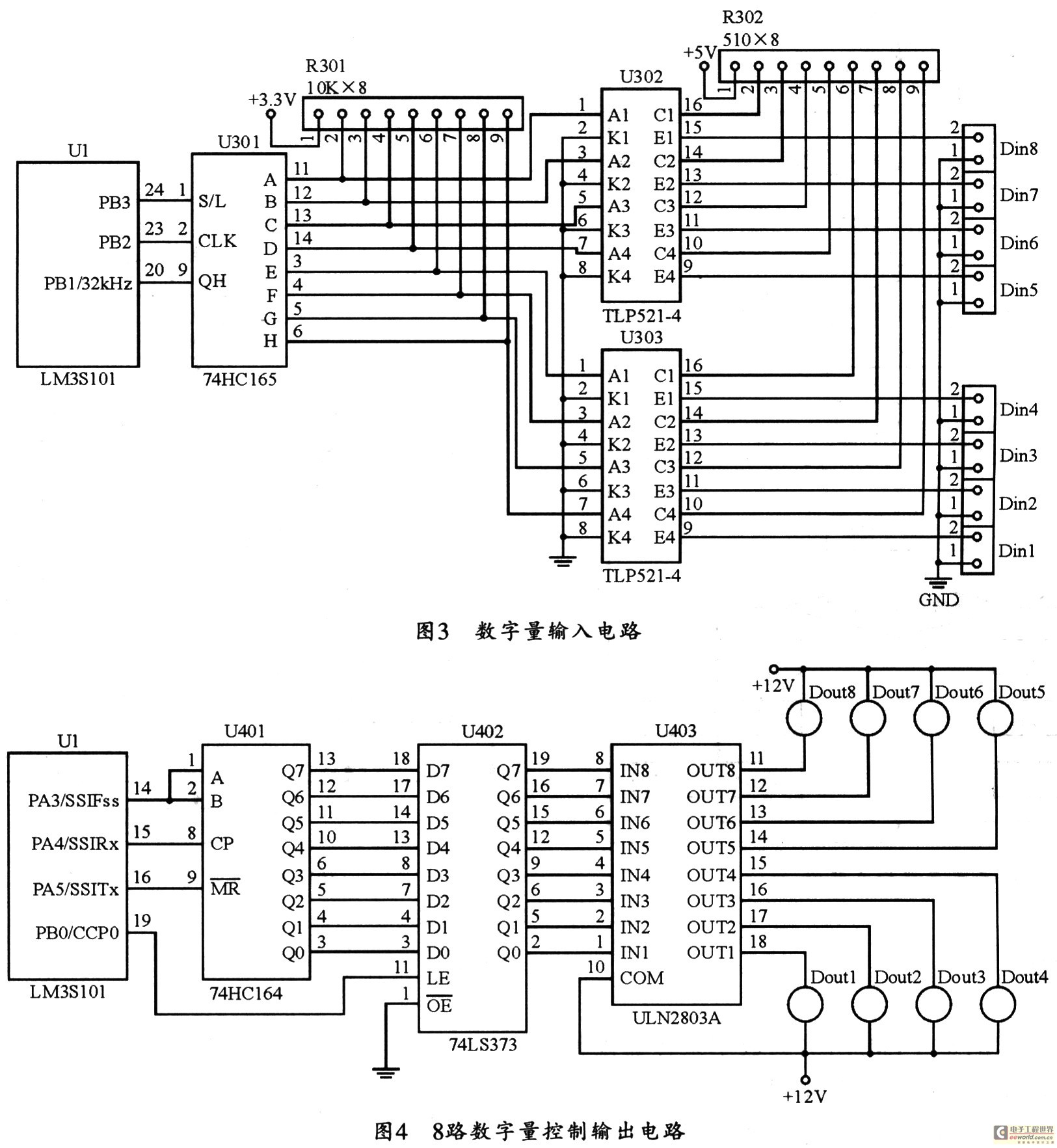
The figure utilizes a controller as the primary equipment for gathering and controlling digital data within an on-site monitoring system. The stability of on-site control operations is crucial to the overall system performance. Therefore, a simple and stable structure...
The power used for realignment is considered a loss in the context of the overall circuit. Due to the hysteresis loss in the saturable-core reactor, the power gain is relatively low. Adding a rectifier to the load circuit can...
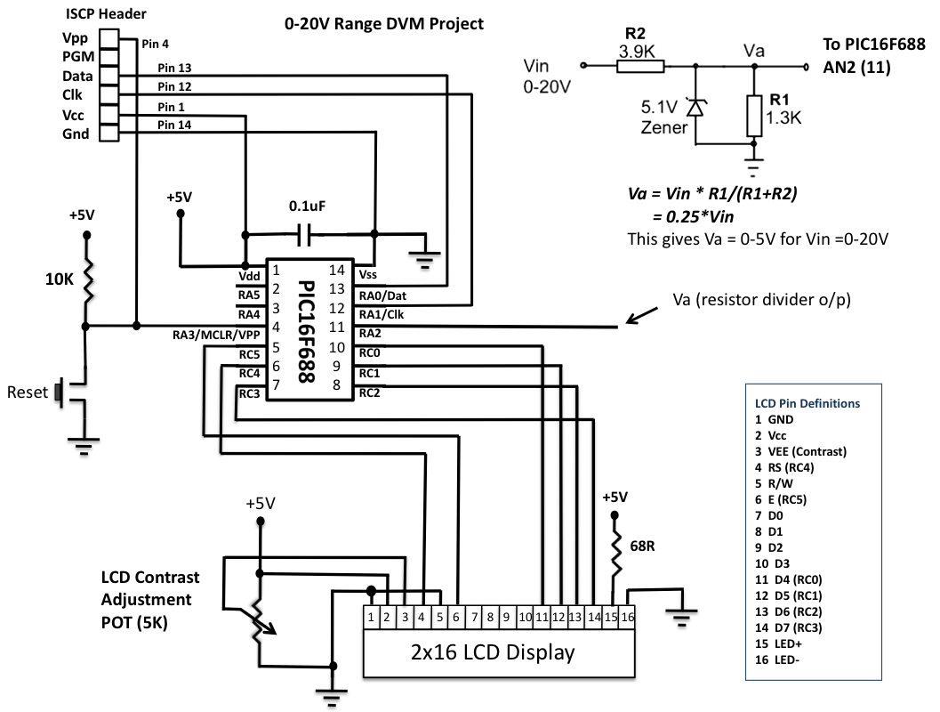
This is another version of an older digital voltmeter (DVM) project that was based on the PIC12F683 microcontroller. The previous version displayed the measured voltage on an LCD driven serially by the PIC12F683 using three I/O pins. The new...
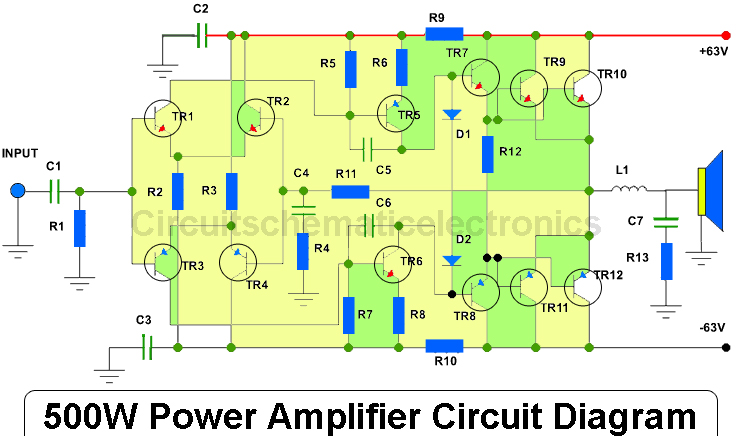
This amplifier has an output power of approximately 500 Watts, with a compatible voltage supply of up to 63 Volts. When operating, the output transistors should be mounted on an adequate heatsink due to the significant heat generated during...
This is a high-quality FM transmitter suitable for use with stereo systems or other amplifiers, providing a strong signal strength with a range of up to 500 meters and a power output of approximately 200 mW. The circuit operates...