
BLW96 RF Amplifier Circuit

The BLW96 transistor is a crucial component in RF (radio frequency) applications, particularly in transmitting equipment that operates within the HF and VHF bands. This transistor is designed to handle high power levels, making it suitable for industrial and military applications where robust performance is required.
In terms of specifications, the BLW96 typically features a maximum collector current rating, allowing for efficient power amplification while maintaining thermal stability. Its construction often includes a metal case, which aids in heat dissipation, thereby enhancing reliability during prolonged operation.
The transistor operates in various classes, including Class A, which is known for its linearity and low distortion, Class AB, which balances efficiency and linearity, and Class B, which is optimized for high efficiency. The selection of the operating class is critical and depends on the specific requirements of the transmitting application, such as power output, efficiency, and linearity.
When designing circuits with the BLW96, it is essential to consider the biasing arrangement, load impedance, and cooling requirements to ensure optimal performance. Proper heat sinking and thermal management strategies must be implemented to prevent thermal runaway and ensure long-term reliability.
Overall, the BLW96 serves as a versatile and powerful solution for high-frequency and high-power applications, making it a valuable component in the design of advanced transmitting systems.BLW96 is a HF/VHF power transistor intended for use in class-A, AB and B operated high power industrial and military transmitting equipment in the h.f. and.. 🔗 External reference
Related Circuits
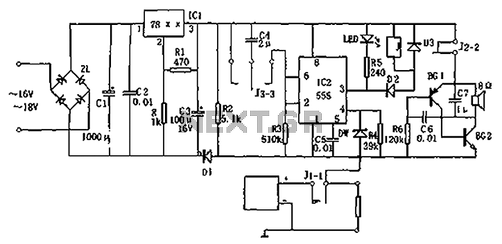
Circuit diagram for a DC power supply protection circuit. The device includes a buck rectifier power supply, a monostable delay circuit, a relay control circuit, and an audio feedback oscillation circuit. The entire circuit operates with a DC voltage...
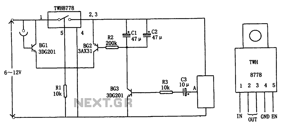
The circuit illustrated in FIG X pertains to automatic circuitry for US recorders. It primarily utilizes a new power switching device, TWH8778, which simplifies the design and eliminates the need for extensive debugging. The TWH8778's configuration and pin functions...
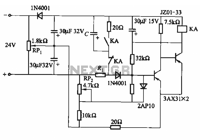
This circuit consists of five transistor time relay circuits designed for time relay exchange. It utilizes two different power supplies, maintaining the same circuit configuration. The delay time can be adjusted by modifying a potentiometer. The parameters for the...
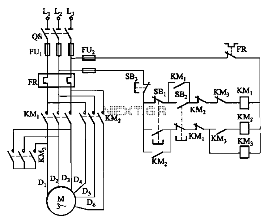
The circuit depicted in Figure 3-96 features a low-speed operation button (SBz), a high-speed operation button (SBi), and a stop button (SB3). In this configuration, a motor is connected in such a way that when the low-speed button is...
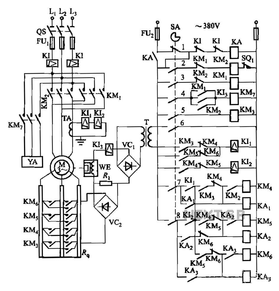
Attached to the wall is a high-rise building construction elevator, an essential piece of vertical transportation machinery. Its drive motor is typically a wound wire induction motor. The main switch and eddy current brake controls are also mounted on...
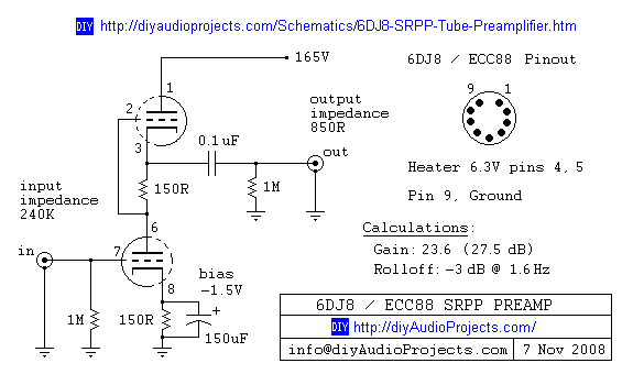
6DJ8 / ECC88 Symmetrical SRPP Tube Preamplifier Schematic. The gain of the preamp is 27 dB (approximately 23.5 times). The 6DJ8 / ECC88 symmetrical SRPP (Shunt Regulated Push-Pull) tube preamplifier schematic is designed to provide a high level of gain...