
Recorders automatic shutdown circuit diagram TWH8778

The automatic circuitry for US recorders, as described, employs the TWH8778 power switching device for efficient operation. The circuit's design emphasizes simplicity and reliability, minimizing the need for extensive adjustments during setup. The TWH8778 serves as a pivotal component, functioning as an electronic switch that controls the power state of the tape recorder based on the input signal conditions.
In operation, the circuit leverages the characteristics of the TWH8778, which activates when the control pin voltage exceeds approximately 1.6V. This threshold is critical for ensuring that the switch remains in a conductive state during normal operation. The touch switch BG1 plays an essential role in initiating the power-up sequence by conducting when pressed, thereby facilitating the necessary voltage drop across resistor R1.
The audio signal's coupling through capacitor C3 to the base of transistor BG3 is crucial for maintaining the operational state of the recorder. When audio playback occurs, BG3 allows current flow to transistor BG2, which is responsible for sustaining the voltage across R1. This feedback loop is vital for maintaining the operational integrity of the tape recorder, ensuring it remains powered during audio playback.
The design also incorporates a significant 1000 µF capacitor at the collector of BG3, which serves to prolong the discharge time constant. This feature is particularly beneficial in scenarios where audio signals may be intermittent or momentarily absent. By allowing BG2 to continue conducting for a short duration even without an audio input, the circuit effectively mitigates the risk of unintended shutdowns, thereby enhancing the overall reliability of the tape recorder during operation.
In conclusion, the automatic circuitry for US recorders utilizing the TWH8778 showcases a thoughtful design that prioritizes functionality and user experience, ensuring that the tape recorder operates seamlessly in response to varying audio signal conditions. As shown in FIG Xin US recorders automatically circuitry. The circuit mainly uses a new power switching device TWH8778, making simple, without debugging. TWH8778 shape and each function of the foot as shown in Figure below, the control terminal feet, when the pin voltage is greater sub-threshold voltage (approximately 1.6V), the electronic switch is closed, O, feet on. When the touch switch touch BG1 and power between the contact sheet, BG1 conduction, so that the voltage drop on R1 TWH8778 closure, tape recorders because the power is turned on and working properly.
If the recorders are playing in the audio signal C3 BG3 coupled to the base, so that BG2 conduction, BG2 there is base current in the conduction state, the voltage drop on R1 also allows the switch to lock TWH8778. When no audio signal, BG1 and BG2 are closing, TWH8778 because feet lose voltage switch off, tape recorders and automatic shutdown.In addition, the large capacitor 1000 F BG3 collector corresponding long discharge time constant, and therefore in the absence of an audio signal can also provide the current for a certain time BG2, BG2 to make a gap in the signal will not be cut, TWH8778 switch will not immediately disconnect, thereby effectively preventing the situation due to erroneous signal the emergence of a gap shutdown.
Related Circuits
With this circuit we can create a altered sound of siren. The oscillator IC1a-b is constituted by two gates NAND, oscillating in very low frequency. This oscillation drive the IC2, that is a electronic switch, which opens and closes...

This relay driver enhances the input impedance using a standard BC547 NPN transistor (or its equivalent). It is a widely used driver capable of operating various relays, including reed relays. Transistors Q1 and Q2 function as a simple common-emitter...

Bootstrapping the substrate of a JFET amplifier minimizes distortion resulting from the non-linearity of the JFET input capacitance. In the accompanying figure, a secondary feedback divider is used to bootstrap the substrate of U1, with R1 set to 500...
This precise one-pulse-per-second clock is constructed using a few common components and is driven by a 50 or 60 Hertz mains supply without a direct connection to it. An audible beep or a metronome-like click, along with a visible...
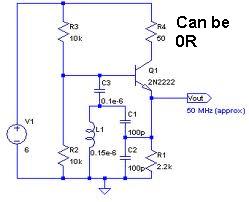
An oscillator circuit capable of generating a high-quality sine wave with a frequency of at least 500 MHz, intended for RFID applications. There have been attempts to utilize a class E oscillator, but the design has not yet been...
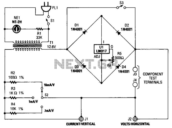
Useful for checking diodes, transistors, triacs, SCRs, resistors, and LEDs, this curve tracer should prove beneficial in the experimenter's lab. It displays the volt-ampere characteristic of a two-terminal device on an oscilloscope. This is a simple block diagram of...