
Booster for Cable Radio

This circuit operates by modulating the audio signals from the local cable network onto a carrier frequency suitable for VHF FM transmission. The design typically includes an audio input stage, a modulation circuit, and an antenna for broadcasting the modulated signal.
The audio input stage captures the audio signal from the local cable network. This can be achieved using a line-level input, which connects directly to the audio output of the cable box or similar device. The signal may require amplification to ensure adequate levels for modulation.
The modulation circuit is crucial as it converts the audio signal into a frequency-modulated signal. This is often accomplished using a voltage-controlled oscillator (VCO) that varies its output frequency based on the input audio signal. The VCO is tuned to a frequency within the VHF band, allowing the signal to be picked up by standard VHF FM radios.
An important consideration in the design is the choice of components, particularly the VCO and the filter circuits that may be used to ensure that the modulated signal remains within the desired frequency range and minimizes interference. Additionally, the circuit may incorporate a low-pass filter to eliminate any unwanted high-frequency noise generated during modulation.
The antenna plays a critical role in transmitting the modulated signal. A simple dipole or monopole antenna can be used, designed to match the operating frequency of the VHF band. Proper placement of the antenna can significantly affect the range and clarity of the received signal on the portable radio.
Overall, this circuit provides a practical solution for accessing local cable network audio content through conventional VHF FM radios, making it a versatile tool for enhancing audio accessibility.With the aid of this circuit it is possible to listen, using a portable VHF FM radio, to listen to stations that transmit only your local cable network. Bo.. 🔗 External reference
Related Circuits
Many antique radios operate on batteries, including tube portables like the Zenith model K-401 and "farm" radios used in rural areas without electrical power. This article provides historical context on battery usage in early radios and offers guidance on...
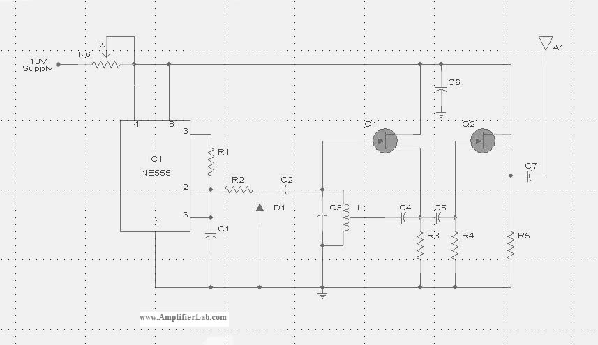
The circuit diagram of the Radio Collar Transmitter is presented here. This circuit is based on the NE555 integrated circuit, which serves as the central component. The Radio Collar Transmitter circuit utilizes the NE555 timer IC to generate a modulated...
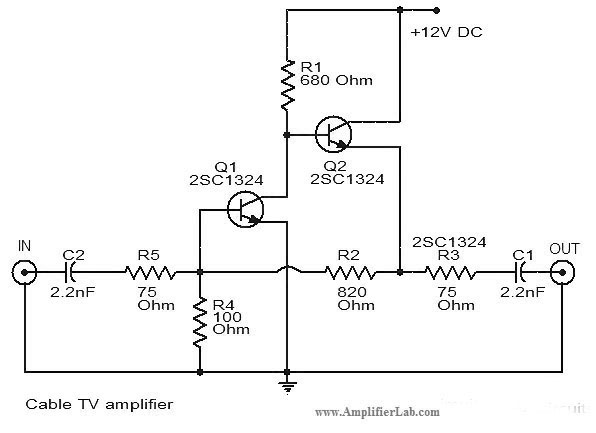
The circuit diagram of a cable TV amplifier has been provided. This cable TV amplifier circuit includes two transistors, Q1 and Q2. The cable TV amplifier circuit is designed to enhance the signal strength of cable television signals, improving the...
Here is a simple radio that is easy to build and inexpensive. In fact, you probably have all the parts you need in your junk box. You'll be surprised at the great reception with this little set. More: The...
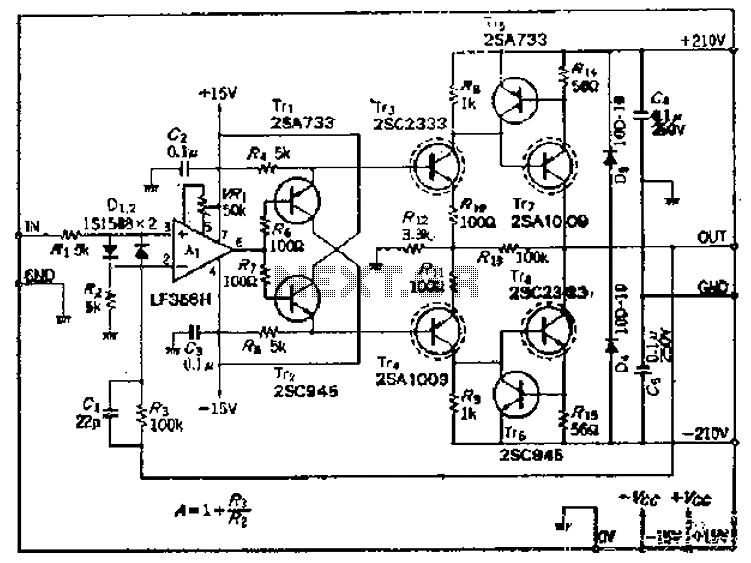
This amplifier circuit operates with an OP amplifier that is power-driven, which leads to the presence of floating voltage errors and necessitates a high-pressure booster for transistor protection. The circuit utilizes a mutual feedback configuration, connecting to the output...
This is basically a crystal radio with an audio amplifier which is fairly sensitive and receives several strong stations in the Los Angeles area with a minimal 15 foot antenna. Longer antennas will provide a stronger signal but the...