
Radio Collar Transmitter Circuit

The Radio Collar Transmitter circuit utilizes the NE555 timer IC to generate a modulated signal suitable for transmission. The NE555 can be configured in astable mode to produce a continuous square wave output, which is essential for creating the radio frequency signal. This signal can then be amplified and transmitted via an antenna.
In the typical configuration, the NE555 is connected with resistors and capacitors that determine the frequency and duty cycle of the output waveform. The frequency is set by the values of the resistors (R1 and R2) and the capacitor (C1) connected to the timing pins of the NE555. The duty cycle can be adjusted by varying R1 and R2, allowing for flexibility in the modulation of the output signal.
The output from the NE555 is then fed into a radio frequency amplifier circuit, which may consist of a transistor or a dedicated RF amplifier IC. This stage boosts the signal strength to ensure that it can be effectively transmitted over a distance. The amplified signal is then connected to an antenna, which converts the electrical signals into radio waves.
Power supply considerations are also critical in the design of the Radio Collar Transmitter. Typically, a battery or a small power source is used to provide the necessary voltage and current for the circuit. Proper decoupling capacitors should be included to filter out noise and ensure stable operation of the NE555 timer.
Overall, the Radio Collar Transmitter circuit is a practical application of the NE555 timer IC, showcasing its versatility in generating modulated signals for wireless communication purposes. Proper layout and component selection are essential for optimizing the performance and range of the transmitter.The circuit diagram of Radio Collar Transmitter has been described here. This circuit is based on the IC NE 555 which is the central part. 🔗 External reference
Related Circuits
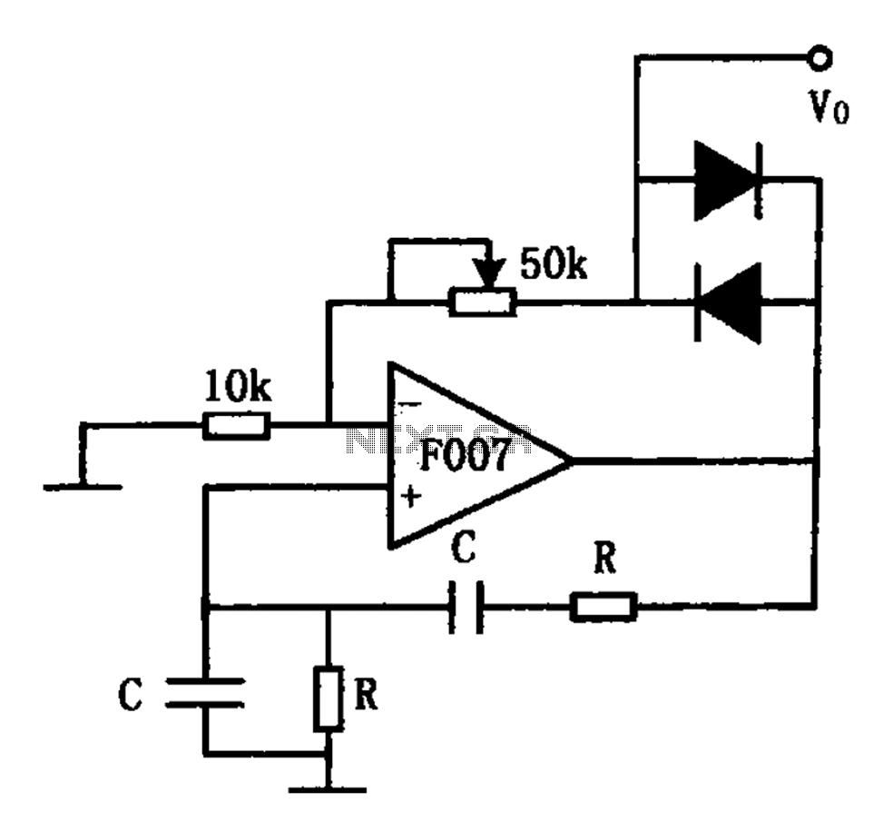
The stable sine wave oscillator circuit is designed to maintain consistent oscillation. The loop gain must be carefully managed; if the gain is excessive, waveform distortion occurs, while insufficient gain can lead to cessation of oscillation. This circuit employs...
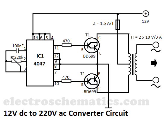
This DIY 12V to 220V voltage converter is built with a CMOS 4047, which serves as the main component of this compact voltage converter that transforms 12V DC into 220V AC. The 4047 functions as an astable multivibrator; at...
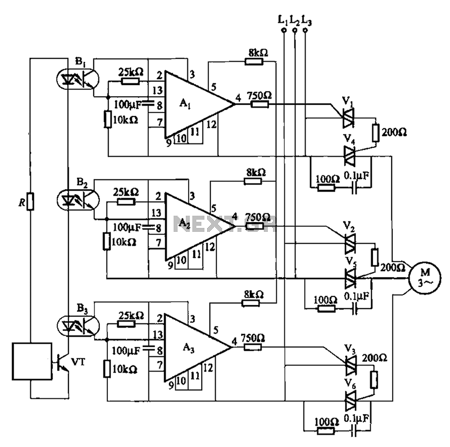
The 331 circuit depicted in the figure utilizes a two-way thyristor for controlling the start and stop functions of a motor. It operates without mechanical contacts, generating no noise or sparks, making it suitable for applications that require frequent...
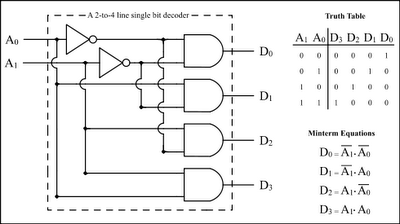
The Encoder and Decoder are different types of combinational circuits used to convert binary information to decimal, octal, and hexadecimal formats, and vice versa. A decoder is a combinational circuit that converts n-bit binary information into 2^n unique outputs....
The operation of the 6CL6 transmitter is quite sophisticated despite the simple appearance of the circuit. The core of the circuit is the electron-coupled crystal oscillator. This circuit integrates the functions of an oscillator and amplifier into a single...
An increasing number of appliances draw a very small current from the power supply. If designing a mains-powered device, one can generally choose between a linear and a switch-mode power supply. However, when the appliance's total power consumption is...