
ir remote extender circuit

The IR remote extender circuit utilizes a Sharp IR detector to receive signals from a standard IR remote control. The received 40KHz modulated signal is processed and converted into a series of electrical pulses. These pulses are fed into a CMOS TLC555 timer configured in monostable mode, which generates output pulses at the same frequency as the input signal. The output from the 555 timer is then used to drive an IR LED, which emits IR light that can be detected by the intended device, such as a television or audio system.
To ensure reliable operation, the circuit design incorporates a few key components: the Sharp IR detector, the TLC555 timer, and the IR LED. The use of shielded cable for extending the output LED is essential to minimize interference and maintain signal integrity over longer distances. The calibration process is crucial, as it ensures that the circuit operates at the correct frequency, allowing for optimal performance of the IR remote extender.
The configuration of the circuit should include appropriate power supply decoupling to prevent voltage fluctuations from affecting the performance of the timer and the IR detector. Additionally, the design may include filtering capacitors to smooth out any noise in the power supply line. The selection of the IR LED must also consider its wavelength and intensity to ensure compatibility with the devices being controlled.
In summary, this IR remote extender circuit provides a practical solution for extending the operational range of standard IR remotes in environments where direct line-of-sight is obstructed. Proper calibration and component selection are essential for achieving the desired performance and reliability.This IR remote extender can increase the range of most simple IR remotes (those operating on a 40KHz modulation) a significant distance. In use, the remote is pointed toward the detector on the circuit, and a button is pressed. The Sharp IR detector then decodes the 40KHz modulated signal into a series of pulses, which trigger a 555 timer.
The 555 outputs pulses which are re-modulated and used to drive an IR LED. The circuit is excellent for use in a large room like a presentation hall where a typical IR remote is a bit weak. By extending the wires to the output LED (using shielded cable) you can control a device where line of sight isn`t available (such as a wall full of TVs in another room).
Only the CMOS TLC555 timer can be used in this circuit. The original NE555 cannot operate reliably at 40KHz. Acceptable substitutions are shown in the parts list. To calibrate the circuit, use a frequency counter. Connect it in parallel with D1 and then ground the base of Q1. Adjust R3 for 40KHz on the counter. If a counter is not available, you will just have to point a remote at the circuit, press a button, and then adjust R3 until it works. This can take a few tries as not all remotes transmit continuously. 🔗 External reference
Related Circuits
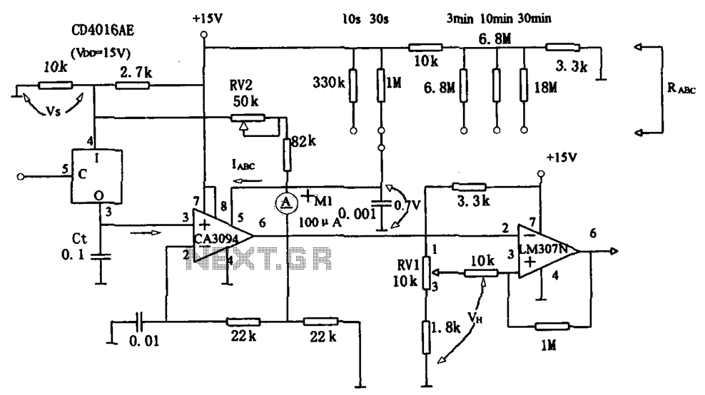
The long timer circuit utilizes an operational amplifier, specifically the CA3094, to control the discharge formula for extended timing. This is typically achieved by adjusting the variable resistor RV1, which alters the timing duration to meet specific requirements. The long...
This circuit illustrates a color sensor circuit diagram. The design is grounded in the principles of optics and digital electronics. The color sensor circuit typically employs a light-sensitive component, such as a photodiode or phototransistor, to detect and differentiate colors...
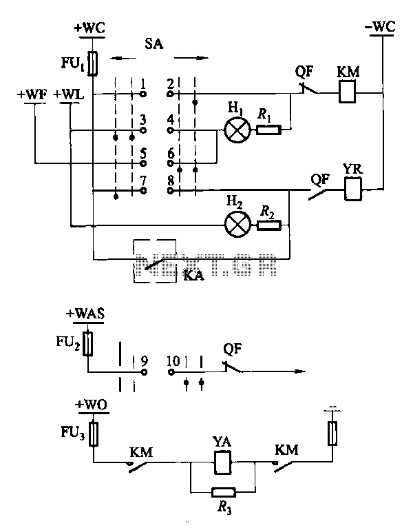
Factories and enterprises operating at voltages of 10 kV and below commonly utilize the CD10 (formerly CD2) type electromagnetic actuator as a circuit breaker. This mechanism features a mechanical anti-jump device. The control signal circuit for the CD10 actuator...
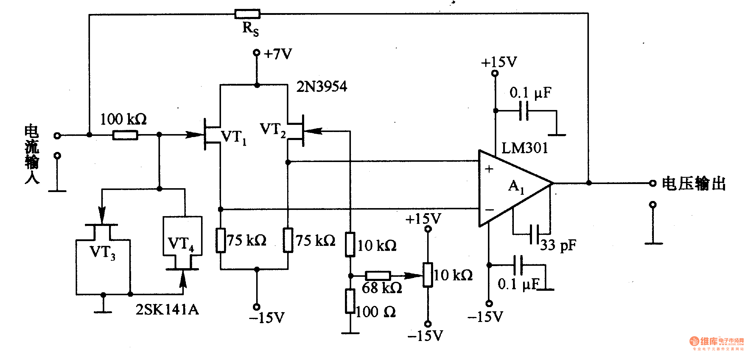
This is a low-input impedance conversion circuit with the reference resistor RS connected to the amplifier's feedback loop, resulting in an input impedance close to zero. The input current flows into the output end of the operational amplifier (Op-Amp)...
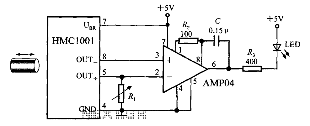
The circuit depicted in the figure includes the HMC1001 magnetic sensor, an operational amplifier (AMP04), and a light-emitting diode (LED), forming a proximity switch circuit. In this application, the operational amplifier functions as a comparator. When a magnet, approximately...
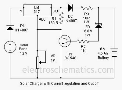
A solar charger circuit is designed to charge lead-acid batteries or nickel-cadmium (Ni-Cd) batteries using solar power. This circuit captures solar energy to charge a 6-volt, 4.5 Ah battery for various applications. It features voltage and current regulation along...