
Brightness Control for small Lamps

The described circuit functions as a switch-mode driver for low-voltage filament bulbs, specifically designed for applications requiring adjustable light intensity, such as photography. The system operates on a portable 3V supply, which can be derived from two AA or AAA batteries.
At the core of the circuit is an integrated circuit (IC1) that generates a square wave signal at a frequency of 150Hz. This square wave is modulated in duty cycle, allowing for control of the average power supplied to the filament lamps. The duty cycle is adjusted via a potentiometer (P1), which alters the width of the positive pulses at pin 3 of IC1.
When the potentiometer is adjusted to its minimum setting, the output pulses are very narrow, resulting in minimal voltage across the connected bulb (LP1). Consequently, the bulb remains off due to insufficient voltage to initiate filament heating. Conversely, as the potentiometer is turned to increase the duty cycle, the width of the pulses increases, allowing more current to flow through the bulb, thus illuminating it more brightly.
The circuit includes a transistor (Q1) that acts as a switch, controlling the connection between the power supply and the bulb. When the pulses from IC1 are wide enough to exceed the threshold voltage required to turn on Q1, the transistor conducts, allowing current to flow through LP1. This mechanism provides a simple yet effective way to control the brightness of the bulbs, making the device suitable for various lighting applications beyond photography.
Overall, this switch-mode driver circuit is a versatile solution for controlling low-voltage filament lamps, with the potential for use in a range of portable lighting applications.Switch-mode driven 1.5V bulbs. This device was designed on request, to control the light intensity of four filament lamps (i.e. a ring illuminator) powered by two AA or AAA batteries, for close-up pictures with a digital camera. Obviously it can be used in other ways, at anyone`s will. Portable unit - 3V battery supply. IC1 generates a 150Hz square wave having a variable duty-cycle. When the cursor of P1 is fully rotated towards D1, the output positive pulses appearing at pin 3 of IC1 are very narrow. Bulb LP1, driven by Q1, is off as the voltage across its leads is too 🔗 External reference
Related Circuits

The circuit is illustrated. It includes a DC power circuit with a power switch (S3) that converts 220V AC voltage through a buck converter (T), a rectifier (UR), and filter capacitors (C3 and C4) to generate a +9V output....
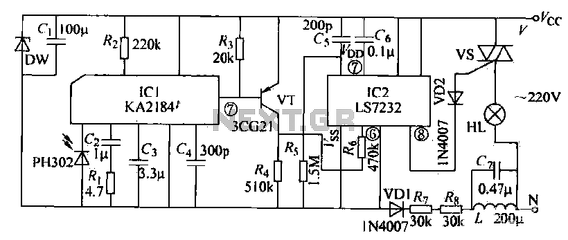
The receiving circuit operates as follows: when the infrared receiver detects a signal from the remote control transmitter, the KA2184 processes this signal, resulting in a low output at the pin. This low output is directly connected to the...
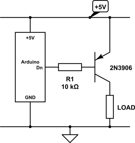
The emitter will consistently be a few hundred millivolts lower than the base voltage in this configuration. With the base voltage set at 5V, the emitter voltage is likely to be around 4.5V, depending on the current drawn by...
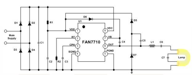
The FAN7710 Ballast Control IC is designed for use with compact fluorescent lamps (CFLs). This IC is developed using Fairchild's unique high-voltage process and system-in-package (SiP) technology. The FAN7710 is a highly integrated ballast control solution that provides efficient operation...
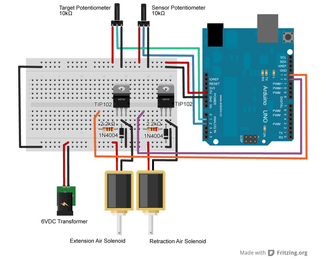
For an upcoming project, a pneumatic ram with a closed-loop control system was required to achieve precise positioning. Due to budget constraints, an off-the-shelf solution was not feasible, prompting the assembly of a custom system using an Arduino, a...
Interest is expressed in constructing a solid-state control system for a Warn 8274 self-recovery winch. The existing control method employs four constant-duty 200 amp solenoids. Two are switched in parallel to connect the field 1 terminal on the motor...