
British Police Car Siren circuit diagram

The circuit utilizes two 555 timer integrated circuits (ICs) to create a sound-generating alarm system. The first timer, configured as an astable multivibrator, operates at a frequency of 1 Hz. This timer continuously switches its output between high and low states, generating a square wave signal. The output of this timer is connected to the control pin of the second 555 timer, which is set up as a frequency generator for sound output.
The second 555 timer alternates its output frequency between 440 Hz (the musical note A4) and 550 Hz, producing a modulated sound that can be perceived as a beeping or alarm sound. The modulation is achieved by using the low-frequency output from the first timer to influence the timing components of the second timer, effectively changing its frequency in a cyclic manner.
To amplify the sound produced by the second timer, a 2N3055 transistor is employed. This NPN power transistor is capable of handling higher currents, making it suitable for driving a loudspeaker. The output from the second timer is fed into the base of the 2N3055, allowing it to control a larger current flowing from the power supply to the loudspeaker.
The circuit is designed with simplicity in mind, making it an excellent project for beginner hobbyists interested in learning about timer circuits and sound generation. The use of widely available components and the straightforward nature of the design facilitate easy assembly and troubleshooting.The 555 on the right is wired as an alarm sound generator and the second 555 timer on the left is a 1 Hz astable multivibrator. The output of the left timer is to modulate the frequency of the right timer. This process will cause the right timers frequency to alternate between 440Hz and 550Hz at a 1 Hz cyclic rate.
The transistor 2N3055 is used to amplify the sound signal to the loudspeaker. This circuit should be nice for newbie hobbysts. We aim to transmit more information by carrying articles. Please send us an E-mail to wanghuali@hqew. net within 15 days if we are involved in the problems of article content, copyright or other problems. We will delete it soon. 🔗 External reference
Related Circuits
This circuit operates two LED strips in pulsing mode, where one LED strip transitions from an off state to gradually lighting up, then dimming, while the other LED strip performs the opposite action. Each strip can consist of 2...
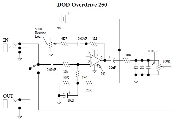
This document provides a circuit diagram for the DOD Overdrive 250 preamp. The DOD Overdrive 250 is similar to the MXR Distortion Plus and several other devices, utilizing a 741 operational amplifier with two diodes on the output channel....
There are monitors that feature only three BNC inputs and utilize composite synchronization (sync on green). This circuit has been specifically designed for such monitors. The design maintains simplicity while delivering reasonable performance. The operational principle is straightforward. The...
This Schmitt trigger circuit is emitter coupled and provides a simple comparator action. The 2N3069 JFET places very little loading on the measured input. Schmitt trigger, emitter coupled, simple comparator, 2N3565, distinct hysteresis loop. The described circuit utilizes an emitter-coupled...

Typical application circuits for the Zheng brick SRS5250S are illustrated in the provided diagram. The SRS5250S features a pin diagram and a processing circuit that allows the user to switch between three operating modes: straight, SRS, and single-channel analog...

This power supply is able to deliver adjustable center-tapped DC from 0 to about 30 volts, as well as AC directly from the Variac and from the main transformer before the rectifier. What's primitive by today's standard is that...