
Fading Leds Circuit

The circuit utilizes a dual operational amplifier integrated circuit (IC1) to generate a triangular waveform, which serves as the control signal for the LED strips. The output of the triangular wave generator is configured to drive the LED strips in a complementary manner. As one strip illuminates, the other fades, creating a visually appealing pulsing effect.
The LED strips are connected to the output of the op-amps through appropriate current-limiting resistors to ensure that the LEDs operate within their specified current ratings. The number of LEDs in each strip can be adjusted between 2 to 5, depending on the desired brightness and power consumption. Each LED strip receives a 9V supply, making it suitable for standard LED configurations while ensuring efficient operation.
To achieve the pulsing effect, the frequency of the triangular wave can be adjusted by varying the resistor and capacitor values in the timing circuit associated with the op-amps. This allows for customization of the pulsing speed, enabling the user to create different lighting effects based on preference. Additionally, the circuit can be designed to include a potentiometer for real-time adjustment of the pulse width or frequency, further enhancing the versatility of the LED lighting system.
Overall, this circuit design effectively combines the properties of operational amplifiers with LED technology to create an engaging lighting experience, suitable for decorative applications or mood lighting.This circuit operates two LED strips in pulsing mode, i.e. one LED strip goes from off state, lights up gradually, then dims gradually, etc. while the other LED strip does the contrary. Each strip can be made up from 2 to 5 LEDs at 9V supply. The two Op-Amps contained into IC1 form a triangular wave generator.. 🔗 External reference
Related Circuits
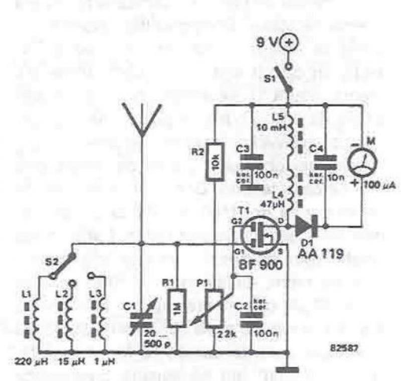
An RF field detector circuit suitable for measuring and verifying the power of antennas and transmitters can be constructed using transistors and common electronic components. This circuit employs a radio frequency transistor, specifically a MOS-FET with two gates. The...
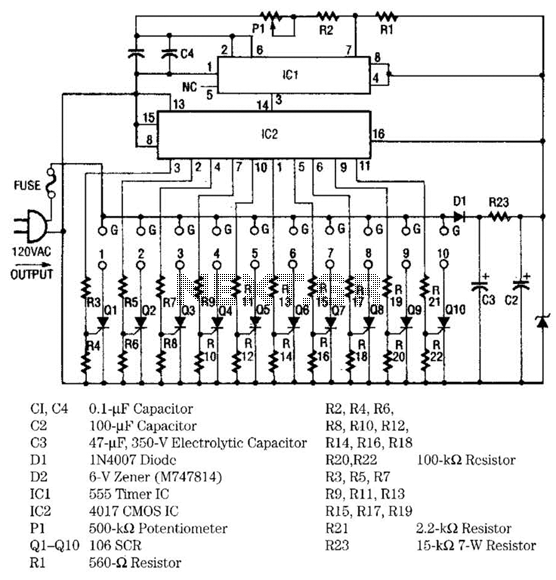
The light sequencer employs two integrated circuits (ICs) and ten silicon-controlled rectifiers (SCRs) to create an alternating current (AC) sequencer. The first IC, a 555 timer, is configured as an astable multivibrator to generate clock pulses for the second...

This circuit protects a PC by requiring a password to boot. After three unsuccessful attempts, the computer must undergo a cold reboot before the password can be attempted again. Software for this system is available; consult the reference for...

The Clock Controller was designed as an exemplary application of the C programming language to manage timer0 interrupts, control a 7-segment LED display, and perform keypad scanning. It offers a 1-bit sink current output suitable for driving devices such...
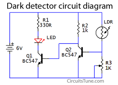
This is a basic dark detector or sensor circuit diagram based on a photoresistor (LDR) and a few components. The dark detector circuit utilizes a photoresistor (LDR) as the primary sensing element. The LDR is a light-dependent resistor that changes...
How to create a hydrogen generator using a 555 timer circuit with Pulse Width Modulation (PWM). This PWM circuit can generate hydrogen on demand. The hydrogen generator circuit utilizing a 555 timer operates by controlling the duty cycle of the...