
Broadband 0.1 to 10Hz filter amplifier

The broadband filter amplifier circuit utilizes two operational amplifiers (op-amps) to achieve signal amplification while filtering out unwanted frequencies outside the specified range of 0.1 to 10 Hz. The circuit is designed for applications that require precise signal processing of low-frequency signals, such as in biomedical instrumentation, seismic monitoring, or low-frequency audio applications.
The first stage of the circuit typically consists of a low-pass filter configuration, which is implemented using one of the operational amplifiers. This stage is designed to attenuate frequencies above 10 Hz, ensuring that only the desired low-frequency signals pass through. The cutoff frequency can be determined using a resistor-capacitor (RC) network, where the values of the resistor and capacitor are selected to achieve the desired -3 dB point at 10 Hz.
The second operational amplifier is configured as a non-inverting amplifier, providing gain to the filtered signal. The gain can be adjusted by selecting appropriate feedback and input resistor values, allowing for flexibility in the amplification level based on application requirements.
Power supply considerations for the op-amps must also be taken into account, ensuring that the supply voltage is sufficient to accommodate the expected output signal swing while maintaining linear operation of the amplifiers. Additionally, bypass capacitors may be included at the power supply pins of the op-amps to reduce noise and improve stability.
Overall, this broadband filter amplifier circuit is essential for applications requiring precise low-frequency signal processing, ensuring that the output signal accurately reflects the input while minimizing noise and interference from higher frequency components. Broadband 0.1 to 10Hz filter amplifier Broadband circuit is composed of two operational amplifiers (0.1-10 Hz) filter amplifiers.
Related Circuits
The video amplifier depicted in the diagram is a well-established design that is both simple and effective. However, there is a risk of damaging the transistors if the potentiometers (black level and signal amplitude) are set to their extreme...
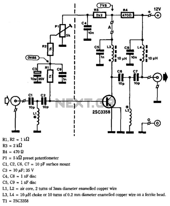
This circuit provides a gain of 10 to 15 dB from 400 to 850 MHz, making it particularly effective in scenarios where the television signal is weak. Additionally, the filters can be customized to meet individual user requirements. Construction...
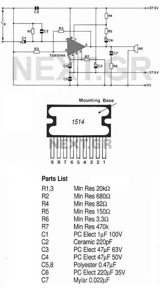
This high-quality audio amplifier is based on the TDA1514A, a 9-pin flat package integrated circuit. The heatsink must be insulated from the ground. The amplifier can deliver 40 watts into an 8-ohm load with a 27.5-volt power rail or...
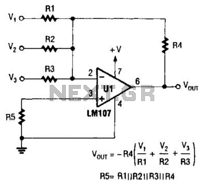
The output of Ul is the sum of Vv, multiplied by the ratio of Rx to Rv, RJRV, and respectively. Resistors R1, R2, and R3 are selected as required for individual gains. Additionally, R4 influences the gain of all...
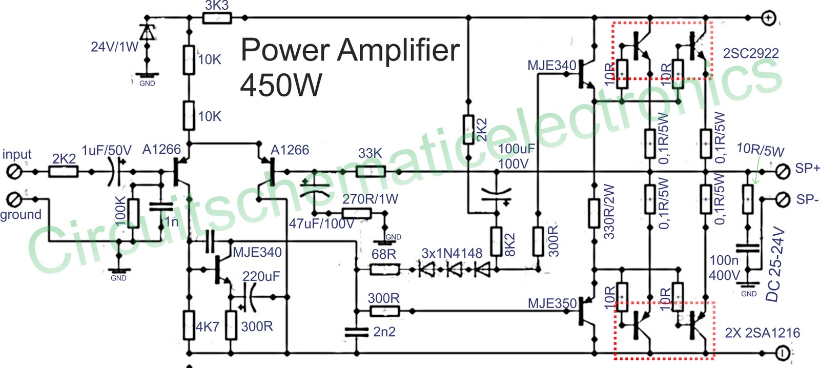
Below is a circuit of power amplifiers with a power output of 450 watts in mono mode. These amplifiers are frequently utilized in high-power applications, suitable for events, and designed for enclosed spaces. This amplifier is appropriate for woofers...
Many designers assert that NFB loop controlled amplifiers are inferior because they degrade the sound. However, it's worth considering what these individuals believe they are actually listening to. The reality is that most vinyl waveforms and CD pits, as part...