
Inverting Summing Amplifier Circuit

The circuit under discussion involves an operational amplifier (Op-Amp) configuration where the output voltage (Ul) is determined by a combination of input voltages and resistive feedback. The input voltage, Vv, is processed through a gain structure that includes resistors Rx and Rv, which set the gain ratio for the operational amplifier. The expression "Rx/Rv" indicates that the gain is contingent on the values of these resistors, allowing for fine-tuning of the amplification factor.
Resistors R1, R2, and R3 serve as adjustable components for individual gains in the circuit. Each of these resistors can be selected or adjusted based on the desired amplification characteristics for each input, enabling tailored performance for specific applications. This selection process is crucial for ensuring that the output meets the required specifications.
Resistor R4 plays a significant role in the overall gain of the circuit, affecting all input signals collectively. By adjusting R4, the designer can control the total gain of the system, ensuring that the output remains within the desired operational range. The interaction between these resistors and the operational amplifier's feedback loop is vital for achieving stable and predictable performance in various electronic applications.
In summary, the described circuit utilizes a combination of resistors to manipulate gain levels for different inputs while maintaining control over the overall output voltage through careful selection and adjustment of component values. This allows for a versatile design suitable for a range of electronic signal processing tasks. The output of Ul is the sum of Vv and multiplied by Rx/Rv RJRV and respectively. Rlj R2, R3 are selected as required for individual gains. R4 affects gain of all these inputs.
Related Circuits
This amplifier features high fidelity (Hi-Fi), high sensitivity, low power consumption, and low distortion, making it an excellent choice for high fidelity sound systems. The process of creating a printed circuit board (PCB) can be accomplished in a few...
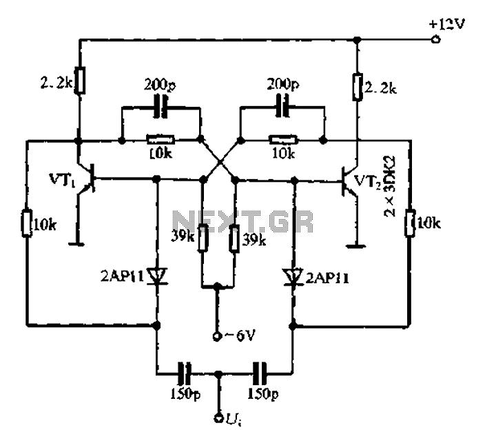
Bistable circuit operating at a frequency of 100 kHz or less. A bistable circuit, also known as a flip-flop, is a type of electronic circuit that has two stable states and can be used to store binary information. This circuit...
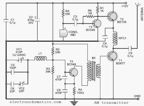
This low-cost AM transmitter is tunable from 10 to 15 MHz with the assistance of a ½J gang condenser VC1, which sets the carrier frequency of the amplitude modulation transmitter in conjunction with inductor L1. Frequency trimming can be...
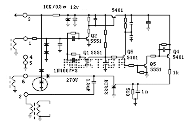
The anatomy of two ignition experiments revealed a common issue, specifically that both ends of the ignition coil are equipped with a diode. This design choice by manufacturers has implications for performance. The ignition coil generates a negative half-cycle...
The inquiry pertains to the connection of lights that flash when a phone rings. This feature is particularly beneficial in noisy environments, such as workshops, where hearing the phone may be difficult. A device designed for this purpose is...
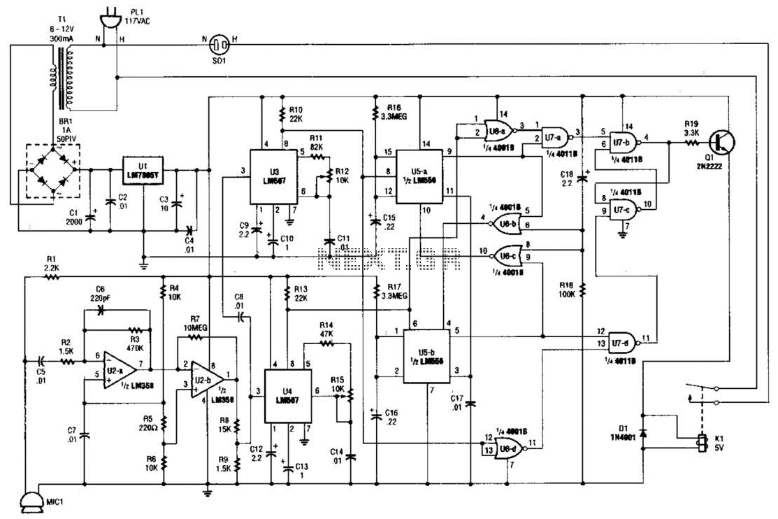
The whistle switch features two tone detectors, each based on an LM567 tone decoder, requiring minimal additional components. It is designed to respond to two or more occurrences of a specific tone or sequence of tones within a defined...