
BTL amplifier composed by a single amplifier

The 13TL amplifier circuit is designed to leverage discrete components to achieve specific performance characteristics, albeit with increased complexity. The BTL (Bridge-Tied Load) amplifier configuration is an efficient design that allows for higher output power while minimizing the number of components required. By employing two amplifiers in a bi-amping configuration, the BTL circuit effectively doubles the output power without necessitating additional power supply voltage, thus enhancing overall efficiency.
The TDA2030A integrated circuit serves as the core of the BTL amplifier configuration, providing robust performance with a maximum output of 34W when powered by a dual 16V supply. This makes it suitable for driving speakers in various audio applications. The circuit's design facilitates a simplified connection to the load by eliminating the need for a center tap on the power supply, allowing for a more straightforward implementation in audio systems.
In practical applications, the BTL amplifier circuit can be used in home audio systems, car audio systems, and other scenarios where high power output is required from a compact design. The dual power supply configuration ensures that the amplifier can maintain high performance across a range of operating conditions, while the discrete component approach allows for customization and optimization of the circuit to meet specific audio requirements.
Overall, the combination of discrete components and integrated circuits in the 13TL and BTL amplifier designs exemplifies modern audio engineering practices, balancing complexity with performance to deliver high-quality sound output.Discrete components 13TL amplifier, the circuit structure is complex, with an integrated power amplifier circuit of BTL amplifier circuit structure is simple, performance and q uite discrete components. Some integrated amplifier on a single integrated circuit produced two amplifier, called bi-amping, the most likely composition BTL amplifier circuit. Figure t-43 by a single power amplifier TDA2030A composed BTL amplifier circuit. This circuit 16V dual power supply voltage, output 34W maximum power. And in a single amplifier, the maximum output power of 14W
Related Circuits
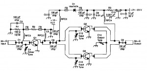
This RF amplifier circuit delivers a power output of 4 Watts at a frequency of 900 MHz. It utilizes Wilkinson power dividers in the base and collector circuits of transistors Q2 and Q3. Two SD1853 driver application transistors are...
The main features of the MULTIWATT Package, a trademark of SGS-THOMSON Microelectronics, include a power amplifier IC designed specifically for car radio applications. It offers a high current capability of 3.5A and can drive a very low impedance of...
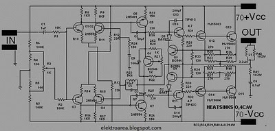
The design of this amplifier aims to enhance the reproduction of complex music and voice. While high electrical properties are emphasized, the primary objective is to achieve superior sound quality, vivid imaging, and exceptional spatial clarity. Although the average...
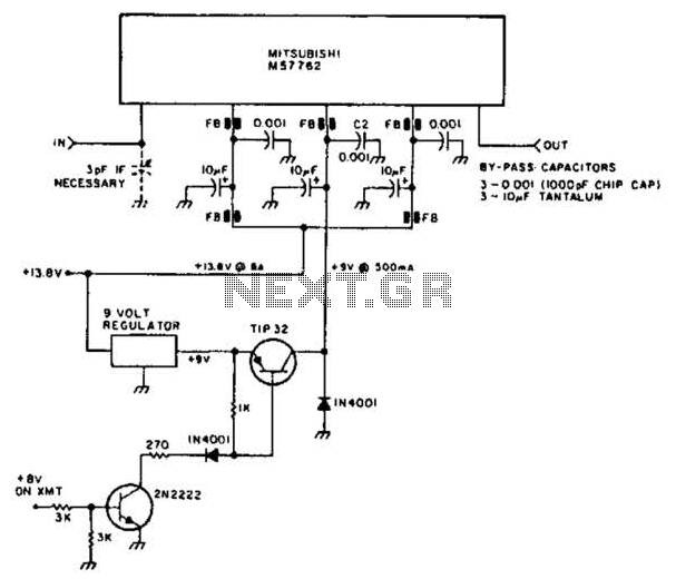
Using a Mitsubishi M57762 amplifier module, this amplifier delivers 20 W output at 1296 MHz. A single 12 V nominal power supply can be used. The Mitsubishi M57762 is a high-performance RF amplifier designed for applications requiring significant power output...
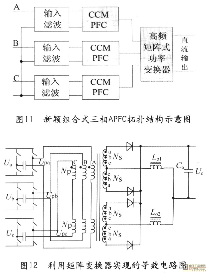
Tape isolate single-phase power factor correction (PFC) that utilizes DC/DC converters, consisting of two cables. The three-phase PFC is formed by connecting three single-phase PFCs in parallel at the output. This configuration is based on a matrix-type DC/DC converter...
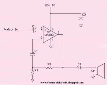
This circuit is an 8W audio amplifier utilizing the LM383 integrated circuit as its primary component. It is designed to be simple, cost-effective, and easy to assemble. Component part list: - C1: 10μF Electrolytic Capacitor - C2: 470μF Electrolytic Capacitor - C3:...