Buffered breakout box

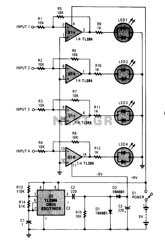
The monitoring circuit consists of four tri-color LEDs driven by an equal number of operational amplifiers configured as inverting amplifiers with a gain of one. Each LED is wired such that it illuminates red when the input to the op amp is high and green when the input is low. The LED remains off when the input is disconnected from the circuit, at ground potential, or when connected to a three-state output in a high-impedance state. Each input has an impedance of 10,000 ohms to prevent circuit loading. The op amps require both positive and negative supply voltages to drive the LEDs effectively. A single nine-volt battery supplies the positive voltage directly, while the negative voltage is generated using a CMOS 555 timer configured as an astable oscillator, which drives a standard diode/capacitor voltage doubler. When connected to the monitoring circuit, the output voltage is slightly under nine volts instead of the expected 18 volts due to loading effects. The circuit draws approximately 16 mA with all LEDs off and between 20 to 30 mA when all four LEDs are on, depending on the number of LEDs illuminated. The use of CMOS op amps significantly reduces quiescent current drain.
The monitoring circuit is designed to provide visual feedback through the use of four tri-color LEDs, effectively indicating the status of the inputs. Each operational amplifier (op amp) functions as an inverting amplifier with a gain of one, ensuring that the output voltage reflects the input conditions accurately. The choice of tri-color LEDs allows for a clear distinction between the two states of the input: high and low. The red color signifies a high input state, while green indicates a low input state, providing immediate visual feedback to the user.
The circuit's input impedance of 10,000 ohms is a critical design choice, as it prevents any significant loading on the communication lines to which it may be connected. This high impedance is essential for maintaining the integrity of the signals being monitored. Additionally, the operational amplifiers require dual power supplies to operate effectively. The positive voltage is sourced directly from a nine-volt battery, while the negative voltage is generated using a CMOS 555 timer configured in an astable mode. This configuration allows the 555 timer to produce a square wave output, which is then used to drive a diode/capacitor voltage doubler circuit, generating the necessary negative voltage for the op amps.
Despite the expectation that the output voltage should be 18 volts (the sum of the positive and negative voltages), the actual output is slightly less than nine volts due to loading effects within the circuit. This emphasizes the importance of considering loading when designing circuits that rely on voltage doubling techniques. The overall current consumption of the circuit is relatively low, drawing about 16 mA when all LEDs are off. However, when all four LEDs are illuminated, the current draw increases to between 20 and 30 mA, depending on the specific states of the LEDs. The use of CMOS technology in the op amps is advantageous, as it significantly reduces quiescent current drain, making the circuit more energy-efficient and suitable for battery-powered applications.
In summary, this monitoring circuit effectively combines visual indication with efficient power management, making it a practical solution for various electronic monitoring applications.The monitoring circuit consists of four tri-color LEDs driven by an equal number of op amps configured as gain-of-one inverting amplifiers. Each LED is wired in the circuit so that it glows red when the input to the op amp is high, and green when the input is low.
The LED remains off when the input is disconnected from a circuit, when it's at ground potential, and when it's connected to a 3-state output that's in the high-impedance state. Each input has an impedance of 10,000 ohms preventing the circuit. from loading communication lines. The op amp requires both positive and negative supply voltages to properly drive the LEDs. Both voltages are supplied by a single, nine-volt battery. The battery supplies the positive source directly. The negative source is supplied via a CMOS 555 oscillator/timer that's configured as an astable oscillator, which is used to drive a standard diode/capacitor voltage doubler. When the 555 is connected to the monitoring circuit, the output voltage is not 18 volts (2 ? 9), but a little under nine volts, due toioading. The circuit draws about 16 mA with all LEDs off; with all four on, it draws between 20 and 30 mA, depending on how many LEDs are high, and how many are low.
The use of CMOS op amps reduces quiescent current drain considerably.


