
Toss-a-coin binary box

The described circuit consists of two main components: the astable multivibrator and the flip-flop. The astable multivibrator is configured to generate a continuous square wave output, oscillating between high and low states. This output is responsible for determining the alternating heads or tails condition. The frequency of the multivibrator can be adjusted using resistors and capacitors, allowing for control over the rate at which the heads or tails condition changes.
The flip-flop serves as a memory element, capturing the output state of the astable multivibrator. Each time the multivibrator completes a full cycle, the flip-flop is triggered to change its state. This mechanism ensures that the output remains stable until the next triggering event occurs, effectively storing the current condition of heads or tails.
To achieve a 50-50 chance of either outcome, the design must ensure that the timing of the multivibrator's oscillation is consistent and reliable. The components used in the multivibrator circuit should be selected for their precision and stability, minimizing any variations that could skew the probability. Additionally, the flip-flop should be of a type that allows for clean transitions between states, reducing the likelihood of glitches during state changes.
In summary, this circuit design efficiently utilizes an astable multivibrator and a flip-flop to create a reliable mechanism for alternating between two states with equal probability. The careful selection of components and design parameters plays a crucial role in achieving the desired performance and reliability of the circuit.Circuit uses an astable multivibrator to vary the heads-or-tails condition, and a flip-flop to store the condition given by the multivibrator Consequently, the circuit is wired so that the flip-flop"s state is changed once for each full cycle the multivibrator goes through to assure an absolutely even 50-50 chance of a heads or tails loss.
Related Circuits
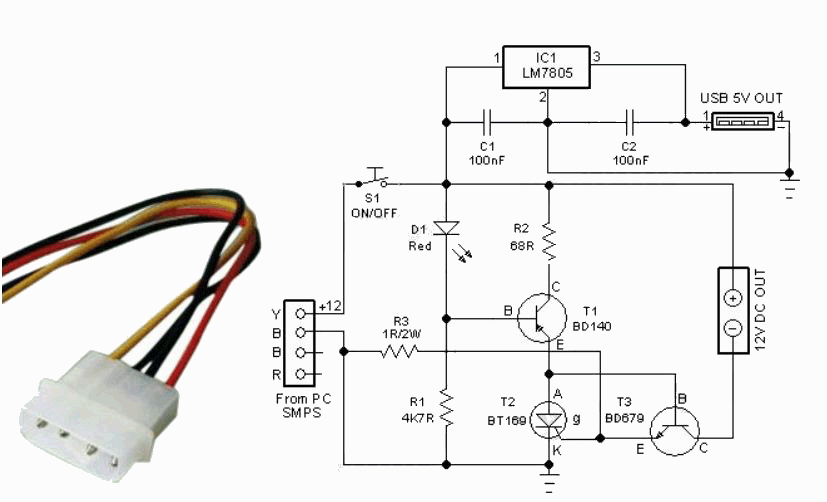
This compact circuit is designed to eliminate the clutter of surplus small AC mains adapters from a desktop environment. The circuit functions as a smart DC power box. The circuit operates by consolidating multiple AC to DC power conversions into...
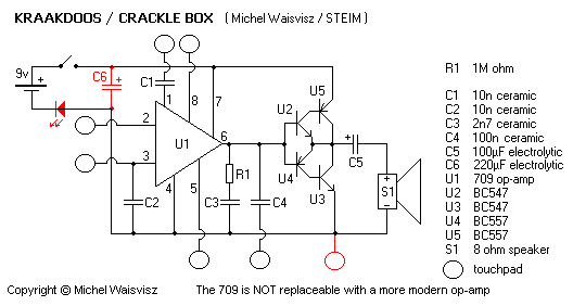
After gathering information about the cracklebox, a decision was made to build one in the spring of 2007. The cracklebox is a solid-state op-amp circuit designed to facilitate interaction through bodily contact. It features several touch points that allow...
When a low or high input voltage in binary form, as obtained from the converter circuit (also provided in the article) fed by a digital voltmeter, is applied, the circuit generates a low pitch for binary 0 and a...

A stomp-box was designed and built for Grammy-winning resophonic guitar player Stacy Phillips. He typically uses two transducers on his Dobro-style instruments: a piezo element mounted internally and a gooseneck-mounted electret microphone positioned approximately one inch above the resonator...

Both versions have the schematic attached. However, the resolution of the schematic is not very high. It is advisable to save the image above or download it to ensure accurate visibility of all details. There is no straightforward method...

500 Series immersion temperature probe, NTC, 100,000 Ohm, ±1.5 °C [±2.7 °F] tolerance, 10 °C to 260 °C [50 °F to 500 °F] accuracy, stainless steel, bullet housing, flying leads (two), 26 gauge Teflon insulation, 4,267 mm [168 in]. The...