
Buffered Crystal VXO

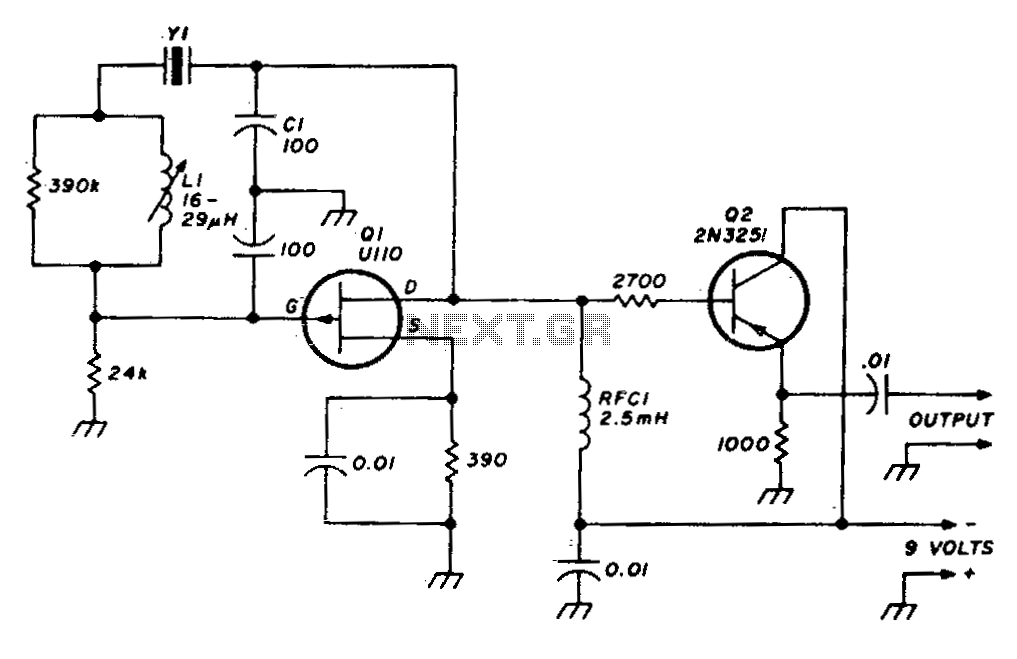
The described circuit is a Variable Crystal Oscillator (VXO) designed for operation within the 20-meter amateur radio band. The circuit features a buffered output, which enhances the stability and integrity of the output signal. The output voltage is specified at approximately 0.2 Vp-p, indicating a low-level signal suitable for further amplification or direct feeding into subsequent stages of a radio system.
Frequency tuning in this VXO is achieved through the use of a variable capacitor (CV1), allowing for fine adjustments of the oscillation frequency. When utilizing a single crystal (Y1), the tuning range is approximately 36 kHz, which provides a stable frequency output due to the inherent characteristics of the crystal. In contrast, when two crystals (Y1 and Y2) are employed, the tuning range increases significantly to about 250 kHz. However, this configuration comes at the cost of reduced frequency stability, which is a crucial factor in maintaining the quality of radio communications.
The inductor (L1) plays a pivotal role in the circuit, as its value directly affects the frequency variation achievable by the VXO. Careful selection of L1 is necessary to optimize performance, particularly in applications such as transmitters, receivers, and transceivers, where stability and frequency accuracy are paramount. The circuit's design allows for versatility in its application across various types of amateur radio equipment, making it a valuable component in the construction of RF systems.The circuit is an VXO with buffered output. It operates on 20-meter amateur radio band with the output voltage about 0.2 Vp-p. The crystal frequency is pulled by tuning the variable capacitor CV1 about 36Khz with only one crystal (Y1), and 250Khz by using two crystals Y1 and Y2. The first configuration stability is much better than using two crystals. However, if you need more frequency variation, use two crystals and you have to pay the cost by getting less stability.
By the way, the value of the inductor L1 is critical to achieve the most frequency variation. You can use it in transmitters, receivers and transceivers with good results. 🔗 External reference
Related Circuits
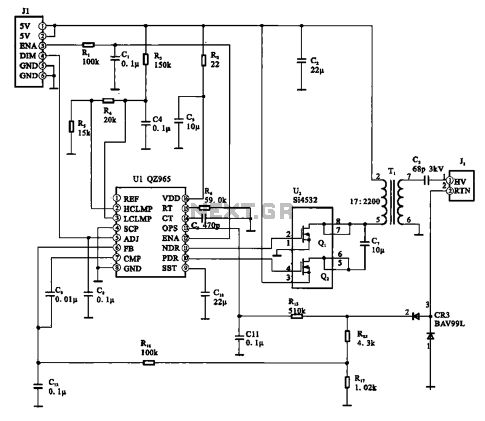
A typical liquid crystal display inverter circuit (OZ965) is primarily controlled by the OZ965 chip. It includes a driving field effect transistor (U2), a step-up transformer, the backlight socket, and associated circuitry. A 5V DC voltage is provided by...
This crystal set has been designed to incorporate features from previous radio models. The #62 radio merges the single-piece design of the #48 set with the dual detector functionality of more recent models. It utilizes a dual honeycomb coil...
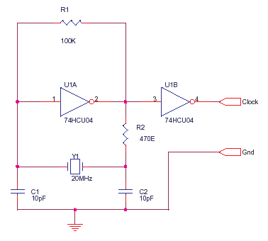
The 74HCU04 is a chip designed for specific circuit applications, while the HCT variant may not be suitable for such configurations. Capacitors C1 and C2 can be utilized up to 33pF, and resistor R2 can be adjusted to achieve...
A crystal radio utilizing a 1N34A germanium diode. It is recommended to use a 24-inch piece of wire for the antenna. The crystal radio circuit described utilizes a 1N34A germanium diode, which serves as a detector for radio signals. The...
A stable variable crystal oscillator (VXO) utilizing 6- or 8-MHz crystals employs a capacitor and an inductor to facilitate frequency pulling on either side of series resonance. The described circuit operates as a variable crystal oscillator, which is crucial in...
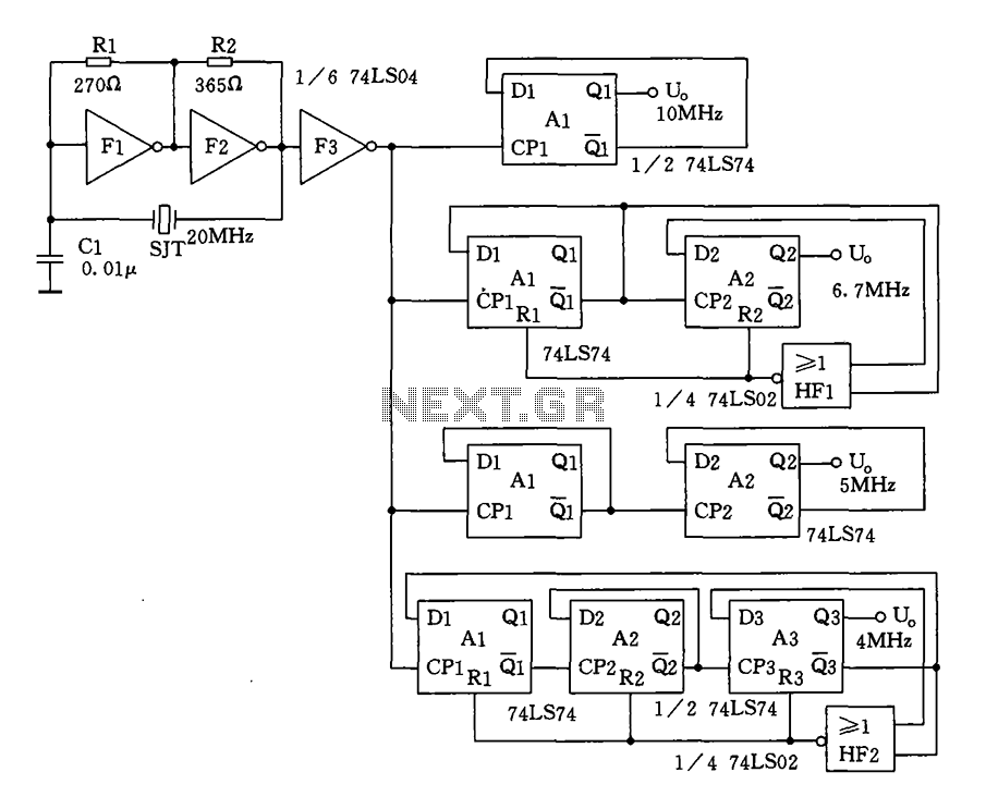
Crystal oscillator and frequency divider (74LS04) circuit diagram. The circuit diagram for a crystal oscillator combined with a frequency divider utilizing the 74LS04 integrated circuit is designed to generate a stable clock signal. The crystal oscillator component typically consists of...