
BUG DETECTOR

The RF detector circuit is designed to identify low-power RF signals, such as those emitted by covert transmitters. The circuit operates by amplifying the incoming RF signal through a two-stage wideband RF amplifier, which enhances the sensitivity of the device, allowing it to detect signals as weak as 1 mW from a distance of 20 feet. The use of a hot-carrier diode as the detection element is crucial, as it converts the RF signal into a baseband signal suitable for further processing.
Once the RF signal is detected, it undergoes filtering to remove unwanted frequencies and noise, ensuring that only the relevant signal is processed. The filtered signal is then fed into an LM3915N integrated circuit, which is specifically designed to drive an LED bar-graph display. The LM3915N interprets the amplitude of the incoming signal and provides a logarithmic output, allowing for a more intuitive visual representation of signal strength. Each segment of the LED bar-graph corresponds to a 3 dB increase in signal strength, enabling users to gauge the proximity of the RF source effectively.
The overall design of the RF detector emphasizes user-friendly operation, with the LED display providing immediate feedback on signal strength and direction. This makes the device particularly useful for applications in surveillance and monitoring, where locating hidden transmitters is critical. The combination of amplification, detection, and visual indication in this circuit creates a powerful tool for RF signal detection in various environments.This rf detector can locate low-power transmitters (bugs) that are hidden from sight. It can sense the presence of a 1-mW transmitter at 20 feet, which is sensitive enough to detect the tiniest bug. As you bring the rf detector closer to the bug, more and more segments of its LED bar-graph display light, which aids in direction finding.
The front end has a two-stage wideband rf amplifier, and a forward-biased hot-carrier diode for a detector. After detection, the signal is filtered and fed to IC1, an LM3915N bar-graph driver having a logarithmic output. Each successive LED segment represents a 3-dB step. 🔗 External reference
Related Circuits

This circuit is operating the room illuminates. The basic component of the circuit is a IC1 (CD4017). Push buttons room are connected by normally wired to the circuit. All circuit is separately by optocoupler, which means that the circuit...

Phase Lock Loop (PLL) FM Detector with 565 PLL IC. The circuit diagram and internal structure of the PLL IC 565 are shown in the given figures. The Phase Lock Loop (PLL) FM Detector utilizing the 565 PLL IC is...
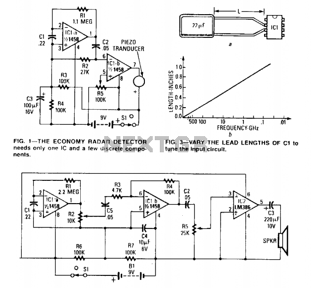
The circuit can be tuned to respond to signals between 50 MHz and 500 GHz. The economy model is illustrated in Figure 1, while the deluxe model is depicted in Figure 2. The first operational amplifier (op-amp) in each...

This circuit is designed to detect electrical wires connected to the mains (live wire). It features an LED for visual indication and a buzzer for audio alerts. As the detector is brought closer to the electrical wire, the LED...
This project is inspired by the DPRG IRPROX project, which features an excellent PCB layout and concept. Appreciation is extended to them for sharing their project, which has significantly accelerated the learning process in PIC programming. The board's pinout...
A second RM output and a sync input have been added to the 555 timer circuit. The sync input is derived from one of Rene Schmitz's voltage-controlled oscillators (VCOs). There are two transistors in the PCB images that lack...