
PLL FM Detector using PLL IC 565

The Phase Lock Loop (PLL) FM Detector utilizing the 565 PLL IC is an essential component in various communication systems, particularly in demodulating frequency-modulated (FM) signals. The PLL operates by locking onto the frequency of the incoming FM signal and extracting the original modulating audio signal.
The core of the circuit is the 565 PLL IC, which consists of a phase comparator, a voltage-controlled oscillator (VCO), and a divider. The phase comparator compares the phase of the incoming FM signal with the output of the VCO. If there is a phase difference, the comparator generates an error signal that adjusts the frequency of the VCO until it matches the incoming signal. This feedback mechanism ensures that the output frequency remains locked to the input frequency.
The circuit typically includes additional components such as resistors, capacitors, and inductors to filter the signal and improve performance. For instance, a low-pass filter may be used to eliminate high-frequency noise from the output, ensuring that only the desired audio signal is processed. The output of the PLL can be connected to an audio amplifier for further amplification and playback.
The internal structure of the 565 PLL IC includes pins for power supply, reference input, feedback, and output. Proper connection of these pins is crucial for the PLL to function correctly. The circuit diagram illustrates the interconnections between the PLL IC and other components, highlighting the signal flow and the role of each element in the overall operation of the FM detector.
In summary, the PLL FM Detector with the 565 PLL IC is a robust solution for demodulating FM signals, providing high fidelity and stability in communication applications. The detailed circuit design and the internal architecture of the 565 IC are fundamental to its functionality, making it a valuable tool in electronic engineering.Phase Lock Loop (PLL) FM Detector with 565 PLL IC. the circuit diagram and internal structure of PLL IC 565 is shown in the given figures.. 🔗 External reference
Related Circuits
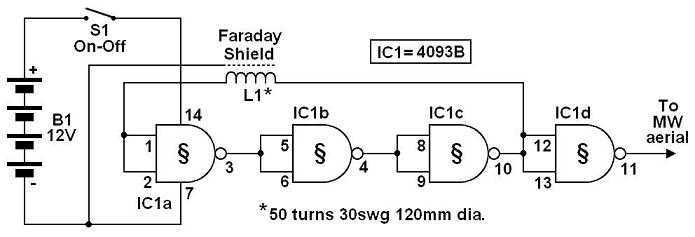
The circuit shown must represent the limits of simplicity for a metal detector. It uses a single 4093 quad Schmitt NAND IC and a search coil -- and of course a switch and batteries. A lead from IC1d pin...
The following circuit illustrates a Water Level Detector Circuit Diagram. This circuit is based on the PIC12F683 microcontroller. Features include the ability of the PIC microcontroller to enter a sleep mode. The Water Level Detector Circuit utilizing the PIC12F683 microcontroller...
This circuit diagram represents a microphone preamplifier, specifically designed to prioritize voice signals over other audio inputs. In its basic configuration, the circuit includes a microphone unit and a change-over switch that connects to an amplifier. When the push-to-talk...
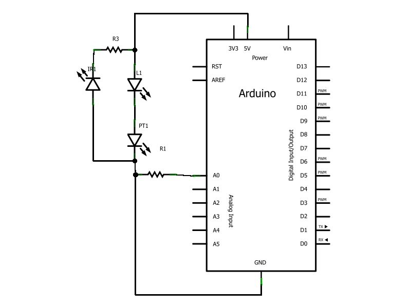
Have you ever wanted to create a line-following robot but found infrared sensors too expensive? If you are located in the UK and have access to a Maplin store nearby, you can purchase infrared transmitters and receivers for just...

The danger always exists when fuel gases such as propane or natural gas are confined to a small area. The toxic gas alarm utilizes a tin-oxide semiconductor. A coil of thin wire is heated by a 12 V battery...
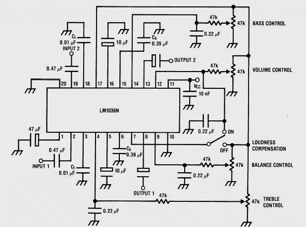
This weblog discusses electronic circuit schematics, PCB design, DIY kits, and electronic project diagrams. It features a stereo tone control circuit built using the LM1036 integrated circuit (IC). This control circuit adjusts bass, treble, volume, and the balance between...