
bug transmitter with PIC16F870 PLL
The described circuit operates as a PLL-controlled transmitter, ensuring frequency stability and ease of digital programming for frequency adjustments within a range of 50 to 150 MHz. The output power is adjustable, typically set at 100 mW, which is substantial for most applications but can lead to excessive battery consumption, particularly when long-distance transmission is not required. The design emphasizes the importance of transmission duration over distance, prompting the need for an efficient power management strategy.
The SSM2167 integrated circuit is employed as a low voltage microphone preamplifier, equipped with variable compression and noise gating capabilities. This component serves to regulate the amplification of audio signals, ensuring that the output amplitude remains consistent regardless of the input signal strength. This is particularly advantageous when dealing with varying audio sources, from quiet whispers to loud jet engines, as it mitigates issues related to clipping and distortion.
The circuit design includes a switch (SW1) that allows the user to select between two audio sources: the raw audio from the microphone or the processed audio from the SSM2167. This flexibility is crucial, as it allows for optimization based on the audio environment. For instances where the audio level is stable and adequate, the SSM2167 may be bypassed to simplify the circuit and conserve power.
Furthermore, the circuit features two potentiometers, designated as P1 and P2, which are utilized to adjust the audio levels. This provides the user with control over the output signal, allowing for fine-tuning based on the specific requirements of the application. It is important to note that while the SSM2167 offers significant benefits in terms of audio processing, its inclusion is optional, and alternative circuits are available on the market that can fulfill similar roles.This frequency of this transmitter is PLL controlled which makes it very stable. The frequency is programmed in digitally way and can be changed very easy. Frequency range is about 50 to 150 MHz and the output power 100mW. The output power is about 100mW and most of the time that is too much. High output power will consume lot of battery time and that is not good. Most of the time you don't need to transmit long distance. The time you want to transmit is more important. The output power is very easy to set and I will explain how to change it to save battery. Analog Devices has made a circuit called SSM2167 which is a " Low Voltage Microphone Preamplifier with Variable Compression and Noise Gating"boy that was long. With simple words you can say it control the amplification of the input audio so the output amplitude is almost constant.
I show you with a picture. At the input you see two areas of audio. The first sound is weaker than the next and the amplitude varies lot. At the output you see the same audio (same frequency) but here is the amplitude almost constant. The audio input can be either a whisper or a Jet engine. The amplitude of the output signal is still the same size and it is under control. No clipping or distortion of audio. So to the bad side of this unit! When the input signal is low (almost silent) the circuit amplification is high and the background noise will be amplified much as well. You can see in the figure. In my construction I have added a switch (SW1) for the audio source to the transmitter. The transmitter can send either the plain audio from the microphone or the compressed audio from the SSM2167.
If you know the audio level is relative constant and in good level you don't need the SSM2167. You don't have to get the SSM2167 circuit, there are several other on the market. If you wish you can exclude it totally, but as I said the unit will be difficult to use in all environments. The function of P1 and P2 are to set the audio level. 🔗 External reference
Related Circuits
PicCon is a PIC microcontroller based radio controller designed for hidden transmitter hunting. When combined with a radio transmitter, it will produce tone sequences and Morse code messages at user-programmed times. It is completely field programmable via DTMF tones,...
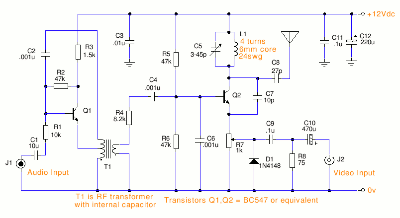
This is a small TV transmitter circuit that transmits in VHF, utilizing negative sound modulation and PAL video modulation. It is suitable for countries that use the B and G system. T1 refers to a type of transformer. The...
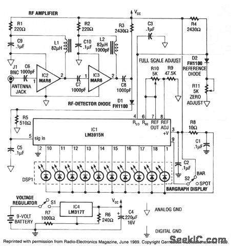
This RF detector can locate low-power transmitters (bugs) that are hidden from sight. It can sense the presence of a 1-mW transmitter at a distance of 20 feet, which is sensitive enough to detect the smallest bug. As the...
This circuit is a long-range infrared transmitter designed to enhance the power of infrared transmitters. Most infrared remotes operate effectively within a range of approximately 5 meters. The complexity of the circuit increases when designing for extended range capabilities. The...

The pressure transmitter circuit data acquisition system utilizes the 1B31, an 18-bit A/D converter (AD1170), and an MCS-51 microcontroller. The configuration, as depicted in the accompanying diagram, features a full-scale output voltage of 10 mV from the pressure transmitter...
This circuit is a highly stable, harmonic-free, long-range FM transmitter designed to operate within FM frequencies between 88 and 108 MHz. It is capable of covering a range of up to 5 kilometers. The circuit features a stable oscillator...