
Build A 20 Amp 13.8 Volt Power Supply
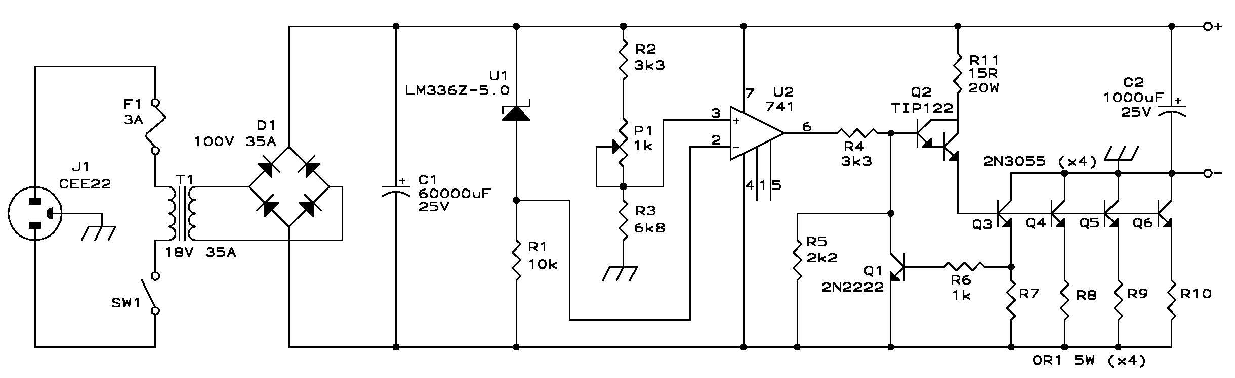
To construct a 20 Amp, 13.8 Volt power supply, the following components and steps are essential for achieving a reliable and efficient design. The power supply will primarily consist of a transformer, rectifier, filter capacitors, voltage regulator, and protection circuitry.
1. **Transformer**: Select a transformer that steps down the primary voltage (typically 120V AC or 240V AC, depending on the region) to a secondary voltage of approximately 13.8V AC. The transformer must be rated for at least 20 Amps to handle the load requirements. An appropriate transformer would typically have a power rating of around 300 VA to ensure sufficient headroom for continuous operation.
2. **Rectifier**: Utilize a full-wave bridge rectifier to convert the AC voltage from the transformer to DC voltage. The rectifier should be rated to handle the peak inverse voltage (PIV) and current requirements. For a 20 Amp supply, diodes rated for at least 30 Amps and 50V PIV are recommended to ensure reliability and longevity.
3. **Filter Capacitors**: After rectification, the output will have a pulsating DC voltage. To smooth this output, large electrolytic filter capacitors are required. The capacitance value can be calculated based on the load current and acceptable ripple voltage. A common configuration may include multiple capacitors in parallel, each rated for at least 25V, to provide adequate filtering and minimize voltage ripple.
4. **Voltage Regulation**: To maintain a stable output voltage of 13.8V, a voltage regulator circuit can be implemented. Depending on the design requirements, either linear regulators or switching regulators can be utilized. Linear regulators will provide lower noise but may generate more heat, while switching regulators can offer higher efficiency and reduced thermal management concerns.
5. **Protection Circuitry**: It is crucial to incorporate protection features to prevent damage to the power supply and connected loads. This can include fuses or circuit breakers rated for 20 Amps, as well as transient voltage suppression devices to protect against voltage spikes. Additionally, thermal protection can be integrated to shut down the supply in the event of overheating.
6. **Output Terminals**: The final design should include output terminals capable of safely delivering the 13.8V DC at 20 Amps. Adequate wire gauge should be used to minimize voltage drop and ensure safe operation. Terminal blocks or heavy-duty connectors may be employed for secure and reliable connections.
This comprehensive approach ensures that the resulting power supply is robust, efficient, and suitable for powering high-current electronic applications. Proper assembly techniques and adherence to safety standards are essential throughout the construction process.Build A 20 Amp 13.8 Volt Power Supply Row circle There are some applications Electronic that you may need to run a relatively high current circuits such as tra. 🔗 External reference
Related Circuits
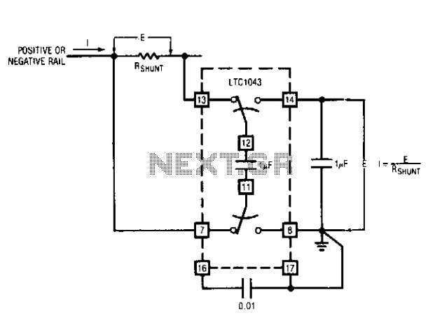
This capability has wide application in battery and solar-powered systems. If the ground-referred voltage output is unloaded by an amplifier, the shunt can operate with very little voltage drop across it, minimizing losses. The LTC1043 can sense current through...
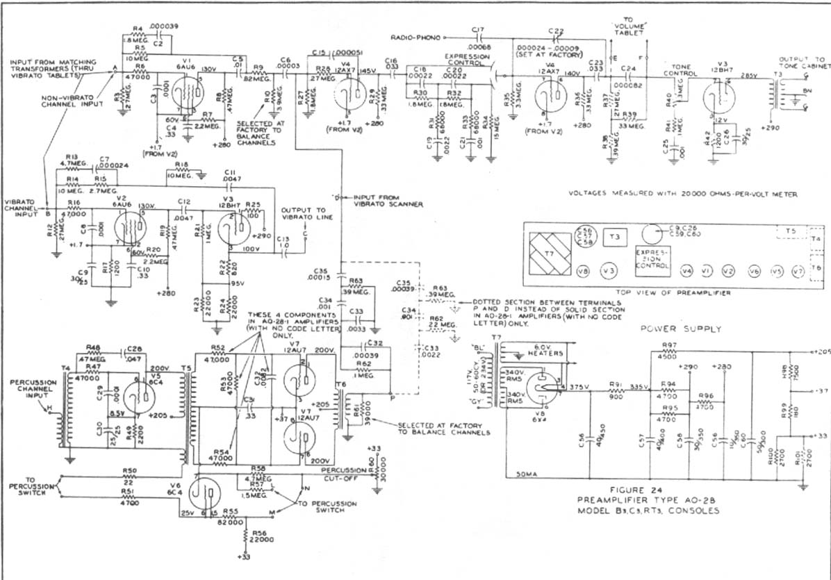
Construct a preamplifier intended to accept a 1/4" keyboard line-level signal and drive a Leslie 147 amplifier. The preamp will utilize a 12AX7 and 12BH7, following the design of a Hammond Organ preamp. The focus will be on the...
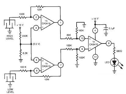
This liquid level sensor electronic circuit diagram utilizes a common CA3410 operational amplifier integrated circuit (IC). The sensor employs two plate sensors (or probes), one designated for detecting high liquid levels and the other for low liquid levels. If...
This article discusses various Teralab Electronics projects involving the 2N2222 transistor. The content is straightforward and informative. The components mentioned can enhance understanding of the projects detailed in this article. For instance, readers can find and purchase the 2N2222...
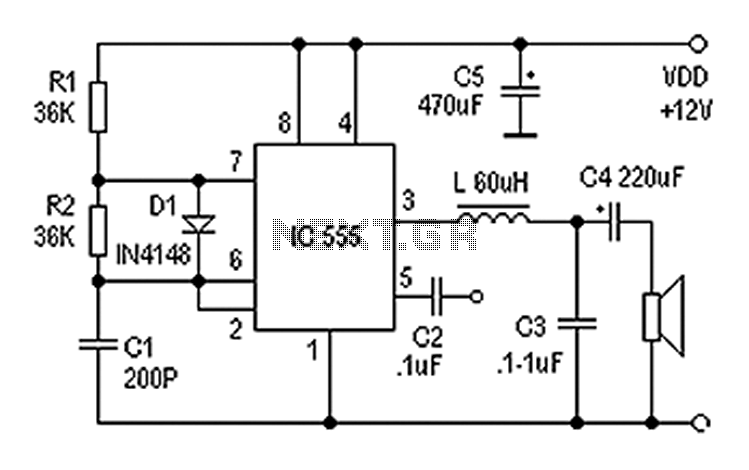
Also known as a digital amplifier, the Class-D amplifier is characterized by its compact size and high efficiency. This circuit utilizes a 555 timer IC to create a Class D amplifier. The 555 timer operates as a controllable multivibrator,...
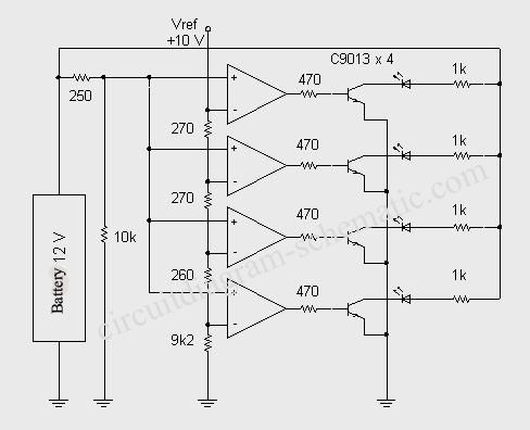
This circuit diagram represents an indicator designed to display a battery voltage of 12 volts. The working principle involves comparing the battery voltage with a reference voltage using the LM324 integrated circuit, which is a low-power quad operational amplifier....