
Build an IR Beam Breaker

The IR Beam Breaker Circuit operates on the principle of modulation and demodulation of infrared signals. The transmitter circuit, built around the 555 timer IC, is configured in astable mode to generate a continuous square wave output at 38 kHz. This signal is fed to an infrared LED, which emits pulses of infrared light. The TSOP 1738 IR sensor module, positioned within the line of sight of the IR LED, detects these pulsed signals. When the infrared beam is interrupted, the TSOP 1738 stops receiving the 38 kHz pulses, resulting in a change in its output state.
The output from the TSOP 1738 is connected to the inverting input of the LM311 comparator. The non-inverting input of the LM311 is typically connected to a reference voltage, which can be set using a voltage divider or a potentiometer. When the TSOP 1738 detects the presence of the 38 kHz signal, its output is high (5V), keeping the output of the LM311 low. Conversely, when the infrared beam is broken, the output from the TSOP 1738 drops to zero, causing the LM311 to switch its output state to high.
This high output from the LM311 can be used to trigger an alarm, activate a relay, or perform any other desired action, such as illuminating an LED or sending a signal to a microcontroller. The circuit's design ensures that it is sensitive to interruptions in the infrared beam while being robust against false triggering from ambient light, making it suitable for security applications. Proper alignment and calibration of the transmitter and receiver are crucial for optimal performance, and consideration should be given to environmental factors that may affect infrared transmission, such as obstacles or reflective surfaces.IR Beam Breaker Circuit Diagram. This is an Infrared beam breaking alarm ideal to use in entry or passages. It is based on the working of the popular IR sensor Module TSOP 1738 which senses 38 kHz Infrared pulses from the IR LED of the transmitter. Range of the circuit is about 5 meters if the transmitter and receiver are properly aligned TSOP 1738
IR sensor module responds to only 38kHz pulsed infrared rays. It will not sense continuous IR ray from the IR LED. So a transmitter circuit(as one in TV remote handset) based on 555 IC is required. Any standard transmitter circuit based on 555 IC can be used. But its output should be 38kHz exactly. TSOP 1738 gives 5 volt output and 5mA current in the off position. That is when IR rays are not available. Its output is current sinking so that when it receives 38kHz IR rays, output becomes zero. Pin 2 of the module should get a supply voltage between 4. 5 to 6 volts. Higher voltage above 6 volts will destroy the device. The module is generally immune to ambient light, but may responds to sources of noice such as electronic ballasts. Out put from the IR module is given to the inverting input of IC1. LM311 is a precision voltage comparator. It looks like the common Op Amps like LM741, CA3130, CA 3140, TL071 etc. But its pin connections and output are different from other Op Amps. 🔗 External reference
Related Circuits
The improved system is called RC-CAM2. It works better and it costs less than my earlier attempt to get a wireless video system on my flying model. The only caveat is that there is some assembly (or disassembly as...
This design is based on a publication by Milan Lulic in the German magazine elektroModell. Lulic's design utilizes surface mount technology (SMT), while this version employs standard off-the-shelf components, making it more accessible for hobbyists. For those interested in...

This circuit features an intermittent siren output and automatic reset. It can be operated manually using a key switch or a hidden switch, and it can also be wired to activate automatically when the ignition is turned off. By...
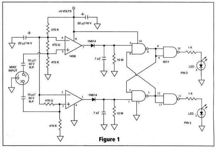
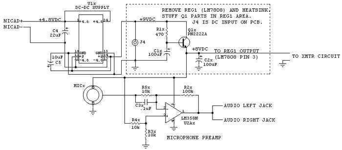
Many things can go wrong in a modern recording studio, but few are as difficult to track down as reversed microphone polarity. When a microphone is placed in front of a sound source, a positive pressure on its diaphragm...

The basic Geiger counter circuit is similar to the previous version, with the addition of components for three optional enhancements: an external power input, a headphone jack, and a digital output, highlighted in red. The external power input is...
The Proteus files can be found. Recently, four pairs of ultrasound MA40S4 receivers/transmitters from Murata were purchased. They function as a pair of ultrasound microphones and speakers. The objective is to build a simple homemade ultrasound sensor for detecting...