
building an ultrasonic sensor

The MA40S4 ultrasound transceiver operates on the principle of emitting ultrasonic waves and receiving the reflected waves from nearby objects. This device is particularly suited for applications in distance measurement and obstacle detection due to its compact size and effective range. The transceiver can be integrated into a circuit that includes a microcontroller, which processes the signals received from the MA40S4.
To construct a basic ultrasound sensor, the following components are necessary: the MA40S4 transceiver pairs, a microcontroller (such as an Arduino or similar), a power supply, and additional passive components like resistors and capacitors to stabilize the circuit. The microcontroller will generate a pulse signal that drives the transmitter, which emits ultrasonic waves. Upon receiving the reflected waves, the transceiver will convert them back into electrical signals.
The distance to an object can be calculated using the time delay between the transmission of the ultrasonic pulse and the reception of the echo. The formula used is Distance = (Speed of Sound × Time) / 2. Given that the speed of sound in air is approximately 343 m/s, the microcontroller can compute the distance by measuring the time taken for the signal to travel to the object and return.
In terms of circuit design, the transceiver should be connected to the microcontroller's digital pins for both transmitting and receiving signals. A suitable power supply must be provided to ensure the transceiver operates within its specified voltage range. Additionally, a simple user interface, such as an LED display or a buzzer, can be incorporated to provide feedback on the detected distance or alert when an obstacle is within a predefined range.
This ultrasound sensor can be utilized in various applications, including robotics for navigation, automated systems for object avoidance, and even in security systems for intrusion detection. The versatility and effectiveness of the MA40S4 make it an ideal choice for DIY electronic projects aimed at distance measurement and obstacle detection.The Proteus files can be found HERE I recently bought 4 pairs of ultrasound MA40S4 receiver/transmiters from Murata. They`re basically a pair of ultrasound microphone/speakers. My goal was to build a simple homemade ultrasound sensor for detecting obstacles and measuring distances.
According to the manufacturer, the MA40S4 has an effective reach of 20cm to 4m, which seems fine.. 🔗 External reference
Related Circuits
This is an ultrasonic motion detector circuit with high movement sensitivity. It can detect even minor air movements, such as hot air rising or wind blowing, when the trimpot is adjusted to a sensitive position. The transmitter emits a...

Shadow sensors are commonly utilized to detect the movement of an individual in a confined space. Numerous previously published circuits exhibit a significant limitation, as they only... Shadow sensors operate by detecting changes in light intensity caused by the movement...
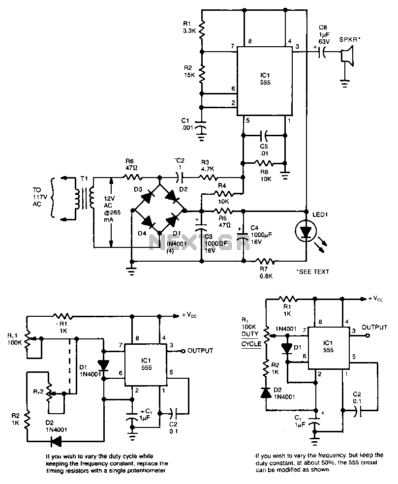
This circuit utilizes a 555 timer integrated circuit (IC) configured as a square-wave generator. The base frequency is approximately 45 kHz, determined by the resistor values R1, R2, and the capacitor C1. The 45 kHz carrier frequency is frequency...
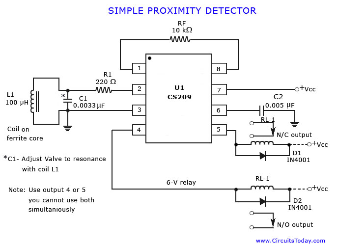
A simple proximity detector circuit diagram and schematic is presented, illustrating how to construct it using the proximity detector IC CS2009A, which is utilized for metal detector applications. The CS2009A is a versatile proximity sensor integrated circuit designed to detect the...
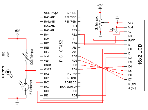
The circuit for the Digital Tachometer/RPM Counter consists of only a few devices. Wire them up according to the following circuit diagram. The PIC used is on a demonstration board, which means the clock, power, and ground pins are...
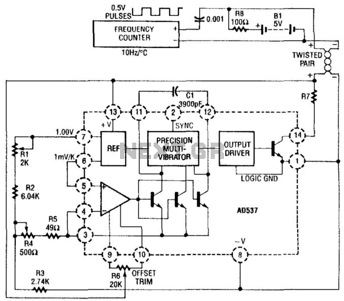
The AD537 utilizes two reference outputs—one fixed at 1 V and the other varying with temperature at a rate of 1 mV per °K. At 0°C, the 1-V reference multiplied by 0.273 balances this voltage to produce a zero...