
build automatic 6 volt 12 volt 24 volt

The described circuit operates as an automatic lead-acid battery charger, capable of charging batteries at three different voltage levels: 6V, 12V, and 24V. The core component of this circuit is the LM338 voltage regulator, which is known for its reliability and versatility in power applications. The input to the LM338 requires a DC supply voltage of approximately 30 volts, which can be obtained from a suitable transformer followed by a rectifier bridge and smoothing capacitor arrangement.
For charging a 6-volt battery, a resistor (R2) is selected to set the output voltage to approximately 7 volts. For a 12-volt battery, the output is configured to 14 volts, and for a 24-volt battery, it is set to around 28 volts. This selection of output voltage ensures that the battery receives the appropriate charging voltage without overcharging, which is critical for maintaining battery health and longevity.
The circuit incorporates a 10 K potentiometer that allows for fine-tuning of the cutoff voltage. This feature ensures that the charger can be adjusted to disconnect the charging current once the battery reaches its full charge state, thereby preventing damage due to overcharging. The cutoff voltage is monitored using an operational amplifier, specifically the IC 741, which serves as a voltage comparator. When the battery voltage exceeds the preset threshold, the output of the IC 741 transitions to a high state, effectively signaling the LM338 to cease current flow to the battery.
An LED indicator is included in the circuit design to provide a visual confirmation of the battery's charged status. When the battery is fully charged, the LED illuminates, alerting the user that the charging process has been successfully completed. This feature enhances user experience and safety by providing a clear indication of the battery's condition.
Overall, this automatic battery charger circuit is a practical solution for maintaining lead-acid batteries, ensuring they are charged efficiently and safely.A simple yet accurate automatic, regulated 6/12/24 volt lead acid battery charger circuit is explained in this article. The circuit switches off the current to the battery as soon as the battery reaches full charge. An illuminated LED at the output indiacates the fully charged condition of the battery. Fundamentally the voltage control and regulat ion is done by the versatile, work horse IC LM 338. An input DC supply volt in the range of 30 is applied to the input of the IC. The voltage may be derived from a transformer, bridge and capacitor network. If a 6 volt battery needs to charged, R2 is selected to produce a voltage of around 7 volts at the output, for a 12 volt battery it becomes 14 volts and for a 24 volt battery, the setting is done at around 28 volts. The above settings take care of the voltage that needs to be applied to the battery under charge, however the tripping voltage or the voltage at which the circuit should cut off is set by adjusting the 10 K pot or preset.
The output supply from the IC LM 338 goes to the battery positive for charging it. This voltage also acts as the sensing as well as the operating voltage for the IC 741. As per the setting of the 10 K preset when the battery voltage during the charging process reaches or crosses the threshold, the output of the IC 741 goes high. 🔗 External reference
Related Circuits

Sometimes it is necessary to power a circuit from a battery where the required supply voltage falls within the discharge curve of the battery. If the battery... Powering a circuit from a battery involves understanding the discharge characteristics of the...
Undervoltage release operates over an extended period. When the power supply voltage drops within the operating voltage range, it triggers the release mechanism, resulting in the rotation of the tripping axle and the disconnection of the circuit breaker. There...
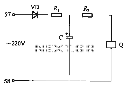
In many instances, the dimmer described here may be integrated into a wall-mounted box that also contains the light switch. It is designed specifically for use with 240 V incandescent lamps. Upon activation, the lamp does not reach full...
The second transistor (T2) is activated by the current passing through the resistor (R1). When a DALI slave unit is connected, this current matches the current flowing through the power transistor (T1). The resistor's value is selected so that...
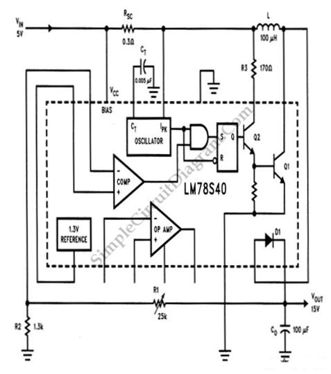
A step-up conversion can be achieved without utilizing a transformer. This circuit is capable of converting a 5V DC source into 15V. It is important to note that there is no power gain. The described circuit employs a DC-DC boost...
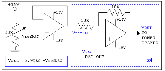
As mentioned in the chapter about the DAC, this circuit shifts the voltage output range. The following diagram explains its operation and structure. The circuit's outputs are connected to the input pins of the power operational amplifiers. The described circuit...