
build good audio buffer

This audio amplifier circuit is designed with a focus on simplicity and effectiveness, making it a suitable option for various applications, including voice amplification and basic audio processing. The circuit typically employs an operational amplifier (op-amp) as the primary amplification element, which is known for its high gain and low noise characteristics.
The input stage of the circuit includes a coupling capacitor, which serves to block any DC offset present in the audio signal while allowing the AC audio signal to pass through. This ensures that the op-amp operates within its optimal input range. The choice of potentiometer value influences the gain and volume control of the amplifier, allowing for customization based on user preference.
The inclusion of a 100 pF capacitor at the input is critical in environments with high RF energy, as it acts as a filter, preventing unwanted high-frequency signals from interfering with the audio signal. The feedback loop, if added, can improve the linearity and overall performance of the amplifier by reducing distortion and increasing the bandwidth.
The output stage is designed to cater to a range of load impedances, making this amplifier versatile for different speaker types. The careful selection of output capacitor values ensures compatibility with various load conditions, thereby maximizing performance and preventing oscillation issues.
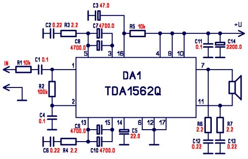
In summary, this circuit provides a balanced approach to audio amplification, combining reliability, ease of construction, and adaptability for diverse audio applications, particularly in settings where low distortion and low impedance drive capability are required.This circuit will amplify voice audio in the range of 50 to 10, 000 cycles with little distortion, and have the ability to drive a low impedance load to 16 ohms. The circuit will run from 6 to 15 vdc and give about 20 dB of gain. To build an inexpensive audio amplifier with little parts count that is very reliable and easy to build and implement.
P arts are available from Radio Shack. If the audio input is biased above ground (audio floats on a voltage) a coupling cap will need installed in the "Audio In" lead to the pot. The pot can be any value from 5 K to 100 K. The 100 pF helps eliminate RF bombardment, making it suitable for higher RF environments. Don`t forget the 100 uF cap or the circuit will oscillate. Many op-amp circuits don`t drive low impedance loads well, this circuit will handle a load impedance to about 16 ohms but doesn`t need to be loaded down to that impedance.
The output cap is a 10 uF non polarized electrolytic for impedance`s to 600 ohms. The output capacitance should be raised to 100 uF for impedance`s to 100 ohms and to 1000 uf for impedance`s below 100 ohms (speaker. ) Operating bandwidth is from 50 cycles to 10 kc. Over 10 kc and the unit suffers from poor slew rate, causing distortion, but for NBFM this bandwidth is acceptable.
Actually, for this purpose slew rate limitations work to our advantage as it helps make the amplifier less RF susceptible. Increased audio amplification can also be had with the addition of a feedback loop. Consult the RS parts substitution manual for examples. 🔗 External reference
Related Circuits

The circuit features a sensitive LM358-based comparator, IC1A, which keeps the monostable IC2A (a 4538) activated as long as an audio signal is detected at the input. The input signal is taken from the hot side of the loudspeaker...
Farmhand has read several pages and is attempting to understand more of the book. It can be challenging to comprehend at times how Tesla was able to achieve certain feats. The provided text reflects an individual's struggle to fully grasp...
The integrated circuit LM386 is a low-power audio frequency amplifier that requires a low-level power supply, typically batteries. It is available in an 8-pin mini-DIP package. The IC is designed to provide a voltage amplification of 20 without the...
This is a diagram of a car audio active loudspeaker utilizing the LF353 operational amplifier from National Semiconductor. For optimal performance, the NE5532 is recommended to split the audio signal into three frequency bands using an active filter. The...
This is a simple circuit designed for an audio amplifier project to control the speaker output relay. The purpose of this circuit is to manage the delay that activates the relay, which connects the speakers to the audio amplifier....
The circuit was designed to create a modular Class A buffer preamplifier to isolate stages in an audio circuit. BF245 is a general-purpose N-Channel JFET used in this design. The modular Class A buffer preamplifier serves as an essential component...