
Building a device from a schematic

Building a circuit from a schematic requires a clear understanding of the components involved and their interconnections. A schematic diagram serves as a blueprint, providing essential information about the electrical connections and functionality of the circuit. Each symbol in the schematic represents a specific electronic component, such as resistors, capacitors, transistors, and integrated circuits.
To successfully construct a circuit from a schematic, one must first identify all components listed in the diagram. This includes verifying the values of resistors, the capacitance of capacitors, and the specifications of any active components. It is also crucial to understand the power supply requirements, including voltage and current ratings, to ensure that the circuit operates correctly.
Next, the physical layout of the components on a breadboard or printed circuit board (PCB) should be planned. Proper placement can help minimize noise and interference, as well as facilitate easier troubleshooting later on. Following the schematic, connections between components should be made using appropriate wiring techniques to ensure reliable electrical contact.
Testing the circuit after assembly is a critical step. This involves using a multimeter to check for continuity in the connections and measuring voltages at various points to confirm that the circuit behaves as expected. If discrepancies arise, the schematic should be referenced to identify and rectify any errors in connections or component values.
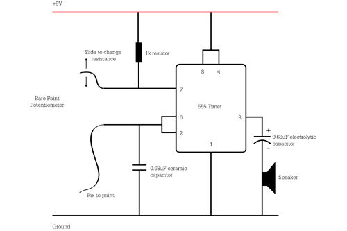
In summary, constructing a circuit from a schematic requires careful attention to detail, a thorough understanding of electronic components, and systematic testing to ensure functionality.A problem we see a lot is that people have a schematic (otherwise knows as a circuit diagram) that they want to build. But they find there are.. 🔗 External reference
Related Circuits
Ensure to verify all connections utilizing the circuit diagram and breadboard schematic available for download from the provided links. This resource can assist during the assembly process. To create a reliable electronic circuit, it is essential to meticulously verify all...
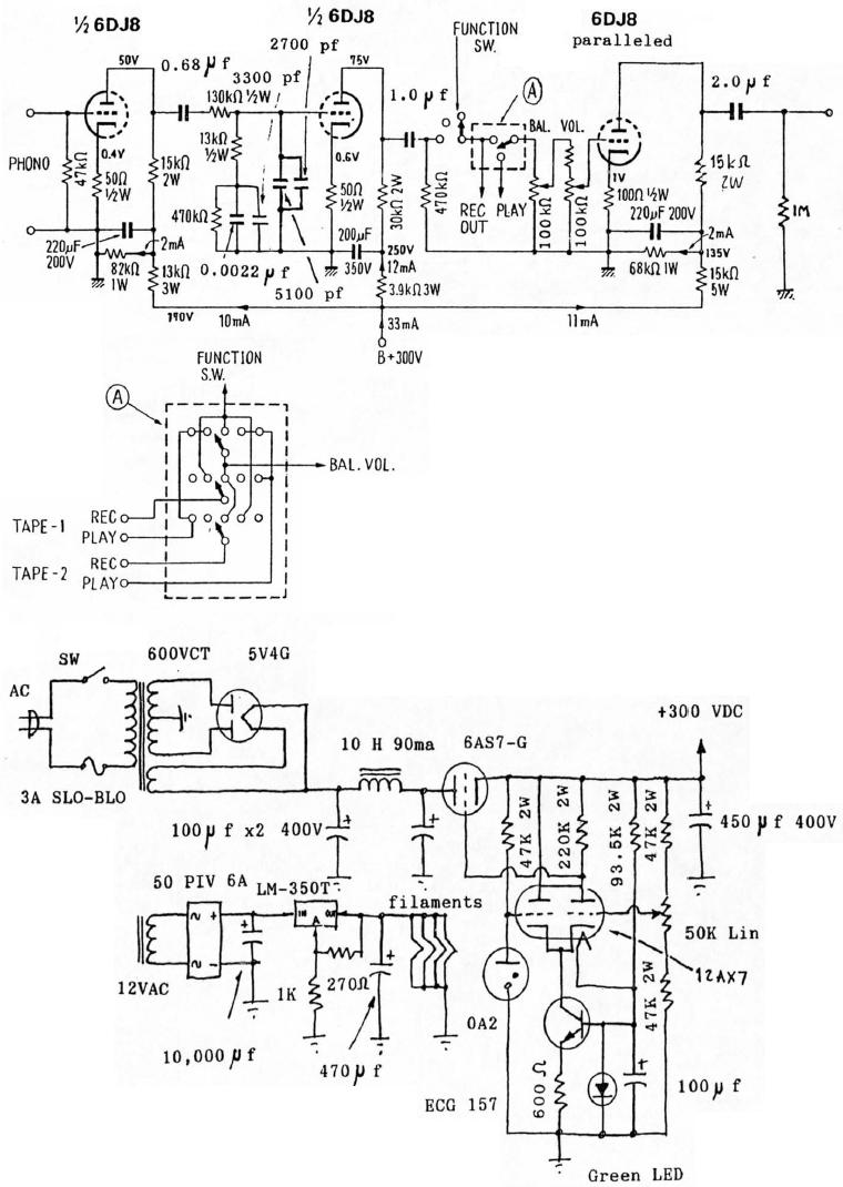
6DJ8 Tube RIAA Phono and Line Preamplifier Schematic. The high-tension (HT) power supply employs tube rectification and regulation. The 6DJ8 tube RIAA phono and line preamplifier schematic is designed to amplify audio signals from phono cartridges and line-level sources, utilizing...
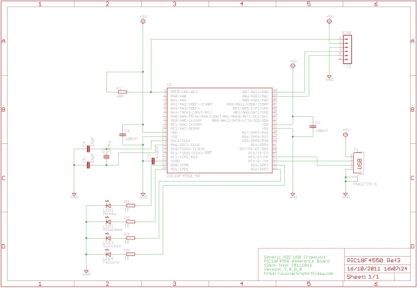
If you have experience with PIC18F microcontrollers and the USB Generic HID standard, you may have noticed the complexity involved in supporting USB on both the PIC18F and the Windows host side. Progressing beyond basic functionalities, such as reading...
This circuit is basically the same as the 10 channel LED sequencer with the addition of solid state relays to control the AC lamps. The relay shown in the diagram is a Radio Shack 3 amp unit (part no....
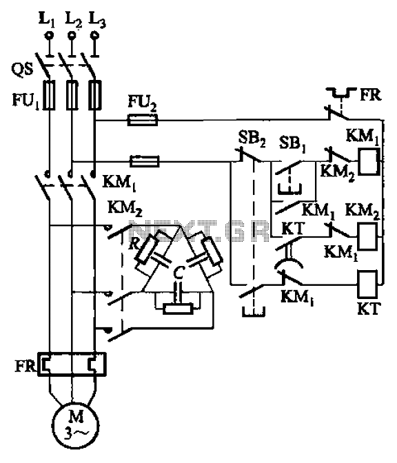
The circuit illustrated in Figure 3-151 consists of capacitor banks arranged in a specific configuration. Figure 3-151 (a) depicts capacitor banks connected in a shaped manner, which is suitable for use with shaped or Y-connected motors. Figure 3-151 (b)...
The circuit presented is an integrated circuit (IC) controlled emergency light. Its key features include automatic activation of the light during mains failure and a battery charger equipped with overcharge protection. In the absence of mains power, relay RL2...