
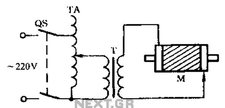
Single-speed motor excitation power from a braking circuit

The circuit design presented in Figure 3-151 is an essential configuration for enhancing the performance of Y-connected motors through the use of capacitor banks. The arrangement in Figure 3-151 (a) emphasizes a shaped connection, which optimizes the reactive power compensation for motors that operate under specific load conditions. This configuration is particularly beneficial for applications where the power factor needs to be improved without significantly increasing the physical footprint of the capacitor banks.
In contrast, Figure 3-151 (b) illustrates a more conventional Y-connected capacitor bank layout, which is straightforward and effective for standard Y-connected motor applications. This arrangement allows for balanced voltage distribution across the phases, ensuring that each phase receives adequate reactive power support.
It is important to note that the shaped capacitor connection is designed to operate at higher voltage levels, typically rated at 600V or more. This requirement arises due to the nature of the electrical stresses encountered in such configurations, making it imperative to select capacitors that can withstand these conditions without failure.
For the appropriate selection of capacitors and resistors based on motor power ratings, Table 3-2 serves as a reference guide. This table provides critical parameters that aid in determining the optimal values of capacitance (C) and resistance (R) necessary for achieving desired operational characteristics in various motor applications, ensuring efficiency and reliability in the overall system design. Circuit shown in Figure 3-151. Figure 3-151 (a) of the capacitor banks connected into shape, it applies to shaped or Y-connected motor; Fig. 3-151 (b) of the Y-connected capaci tor banks, it applies to Y-connected motor. Shaped capacitor using connection, the required electrical smaller capacity, but requires higher voltage value (600V or more). Different power motors, C and R selection Table 3-2.
Related Circuits
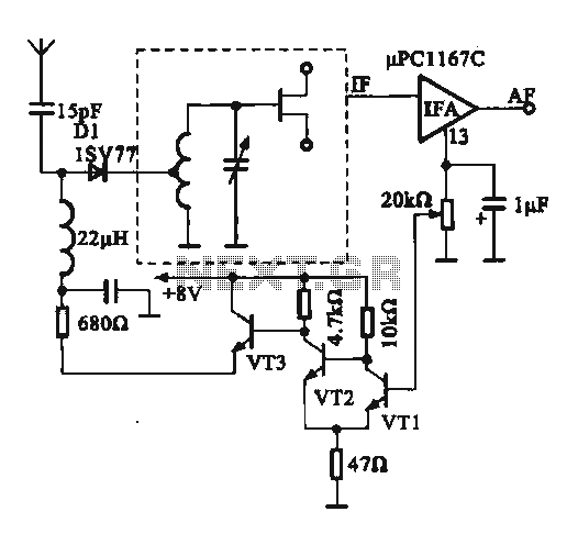
This circuit illustrates an FM modulator with a strong and weak signal switching mechanism. The circuit diagram 3-14 (a) depicts mechanical switches, including a worker selector switch that allows for signal strength selection. Figure 3-14 (b) demonstrates the implementation...

This second-order low-pass filter utilizes a 741 operational amplifier and can be tuned from 2.5 kHz to 25 kHz. The circuit is beneficial in audio and tone control applications. R1 and R2 are ganged potentiometers. The described circuit features a...
The circuit diagram illustrates a three-phase motor equipped with an inspection circuit designed to detect broken bars. The circuit for a three-phase motor with a broken bar inspection system typically consists of several key components that work together to monitor...
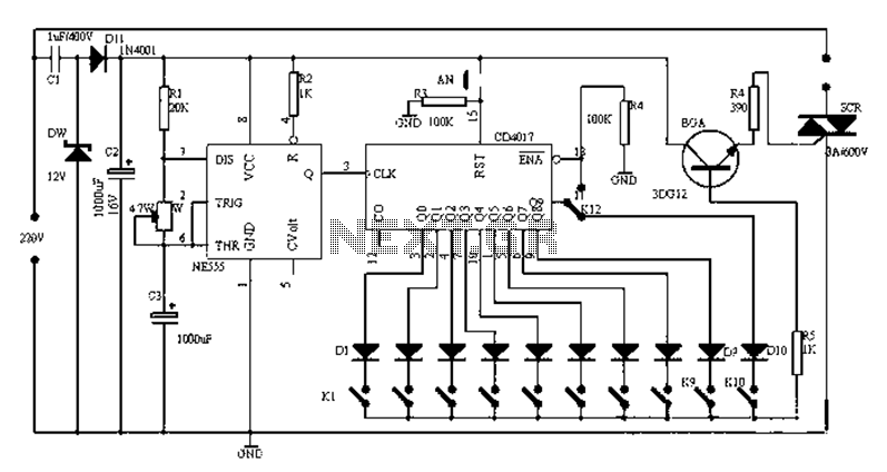
Figure 1-1 illustrates a general-purpose timer capable of timing intervals ranging from 5 minutes to 18 hours. The timing cycle can be adjusted to span from 5 minutes to 20 hours, with a maximum control time of 18 hours....
This code lock circuit is an electronic combination lock designed for daily use. It only responds to the correct sequence of four digits entered remotely. If an incorrect key is pressed, the lock resets. The lock code can be...
The fundamental issue presented is the perception that logic gates in a circuit seem to generate power from nothing, which contradicts the principles of physics. For instance, consider two NOT gates connected in series. It appears that the first...