
Building a Wireless Temperature Sensor

The wireless temperature sensor circuit integrates several key components for effective temperature measurement and data transmission. The LM324 or LM2902 operational amplifiers are utilized to buffer the voltage signals, ensuring that the input from the thermistor voltage divider is stable and accurate. The LM331 voltage-to-frequency converter translates the analog voltage into a frequency signal, which is then transmitted wirelessly via an RF module. The choice of a 47nF capacitor at pin 5 of the LM331 is crucial for setting the output frequency within the acceptable range for the RF link, which is limited to a maximum bit rate of 2400 bps.
The design emphasizes the importance of a regulated power supply to maintain accuracy in temperature readings, as fluctuations in supply voltage can directly affect the thermistor's output. The Arduino microcontroller serves as a versatile solution for receiving the frequency signal and converting it back into a temperature reading. The FreqCounter library facilitates frequency measurement, and the included Arduino code demonstrates how to calculate temperature based on the frequency output.
To enhance accuracy, it may be beneficial to calibrate the system by determining the constants C1 and C2 experimentally, allowing for adjustments based on real-world performance. This calibration process involves measuring the frequency output at known temperature points and using these measurements to refine the temperature calculation algorithm. Overall, the wireless temperature sensor circuit provides a practical and efficient solution for remote temperature monitoring applications.A wireless temperature sensor so that temperature measurements can be made anywhere within the range of the transmitter and the receiver. There are many ways to achieve this. One of the simplest ways is to use a voltage to frequency conversion chip along with an analog temperature sensor such as LM335 or a thermistor, and then transmit the modulated frequency signal via an RF data link module.
Alternatively, we can use a digital temperature sensor and sending the sensor readings over RF serial data link digitally. In this post I will stick with the first approach. Here the 1/4 LM324 (or LM2902) forms a voltage follower to buffer the input voltage from the resistor-thermistor voltage divider, and the divider output is fed into an LM331 voltage to frequency converter.
The LM331 portion of the circuit was taken directly from the reference design. The capacitor at pin 5 needs to be adjusted so that the maximum frequency output from the oscillator is below the maximum bit rates supported by the RF link. The RF data transmitter I used has a maximum bit rate of 2400 bps and thus I used a 47nF capacitor and the oscillation frequency is around 700 Hz under room temperature.
The frequency output from LM331 is again buffered via another 1/4 LM324 (or LM2902) before feeding into the RF data link transmitter. This voltage to frequency circuit is arguably not the most accurate one and you could improve your accuracy by adding an op-amp integrator as illustrated in the datasheet, but for the temperature measurement application we are discussing here, this simple circuit is accurate enough.
According to the LM331 data sheet, the timing components need to have very high stability in order to achieve a high level of accuracy and minimize frequency drift. The picture above shows the finished transmitter portion of the temperature sensor. Note that the power supply must be regulated in order to obtain accurate readings since it is referenced by the thermistor voltage divider.
I could have built the receiver using another LM331 as a frequency to voltage converter and use the voltage readouts to calculate the temperature readings. But then I would need to use an A/D converter to convert the signal back to digital form in order to perform the calculation.
To simplify the design, I used an Arduino MCU (ATmega328) to measure the frequency output from the RF data link receiver directly. The following picture shows the setup on the receiver end. With the transmitter and receiver working, now we need to convert the received frequency readings back to the temperature readings.
Again, to help you understand how the calculation is done I have included the reference schematic below: Although the two constants C1 and C2 can be determined by the theoretical values of the components, it is probably simpler to obtain them experimentally by measuring two or more frequencies at different temperature points. Below is the Arduino code I used. The FreqCounter library I used can be found here. Note that parameters in the code are tailored specifically for the type of thermistor I used and they are also affected by the transmitter supply voltage (in my case the transmitter operates on 5V).
You will need to re-calculate the parameters based on the equations I gave above. #include
Related Circuits
This sensor circuit was designed to assist in parking a car near a garage wall while reversing. LED D7 lights up when the distance from the bumper to the wall is approximately 20 cm. LEDs D7 and D6 illuminate...
The Air Flow Sensor Circuit describes sensing air flow using the microcontroller PIC16C781. Air flow is detected by the cooling effect of air. The Air Flow Sensor Circuit utilizes the PIC16C781 microcontroller to effectively measure air flow by leveraging the...
A sensor is being developed to measure snowfall. If this sensor can be produced at a low cost, the potential of the Internet can be harnessed to gather extensive data across large areas. Current popular weather data collection platforms,...
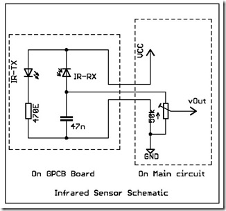
The following circuit illustrates a simple infrared sensor module circuit diagram. Features include a simple infrared sensor module and flame detection. The simple infrared sensor module circuit operates by utilizing an infrared (IR) transmitter and receiver pair. The IR transmitter...
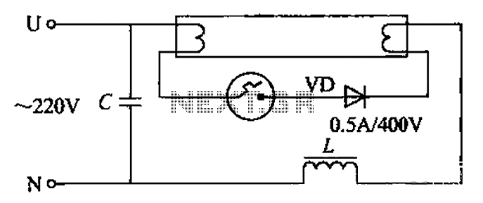
By incorporating a second pull tube into the circuit during the starter ionization phase, the positive half-cycle diode conduction results in an approximate DC current flow. This current is rectified, and due to the small ballast impedance, the instantaneous...
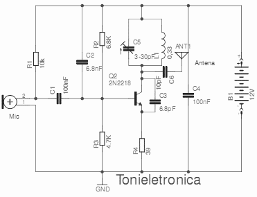
This small transmitter can reach distances of more than 1 km under favorable transmission conditions. Modulation can be achieved using a microphone, such as an electret microphone, or another audio source. The transmitter includes a coil made of 5...